 EN
EN

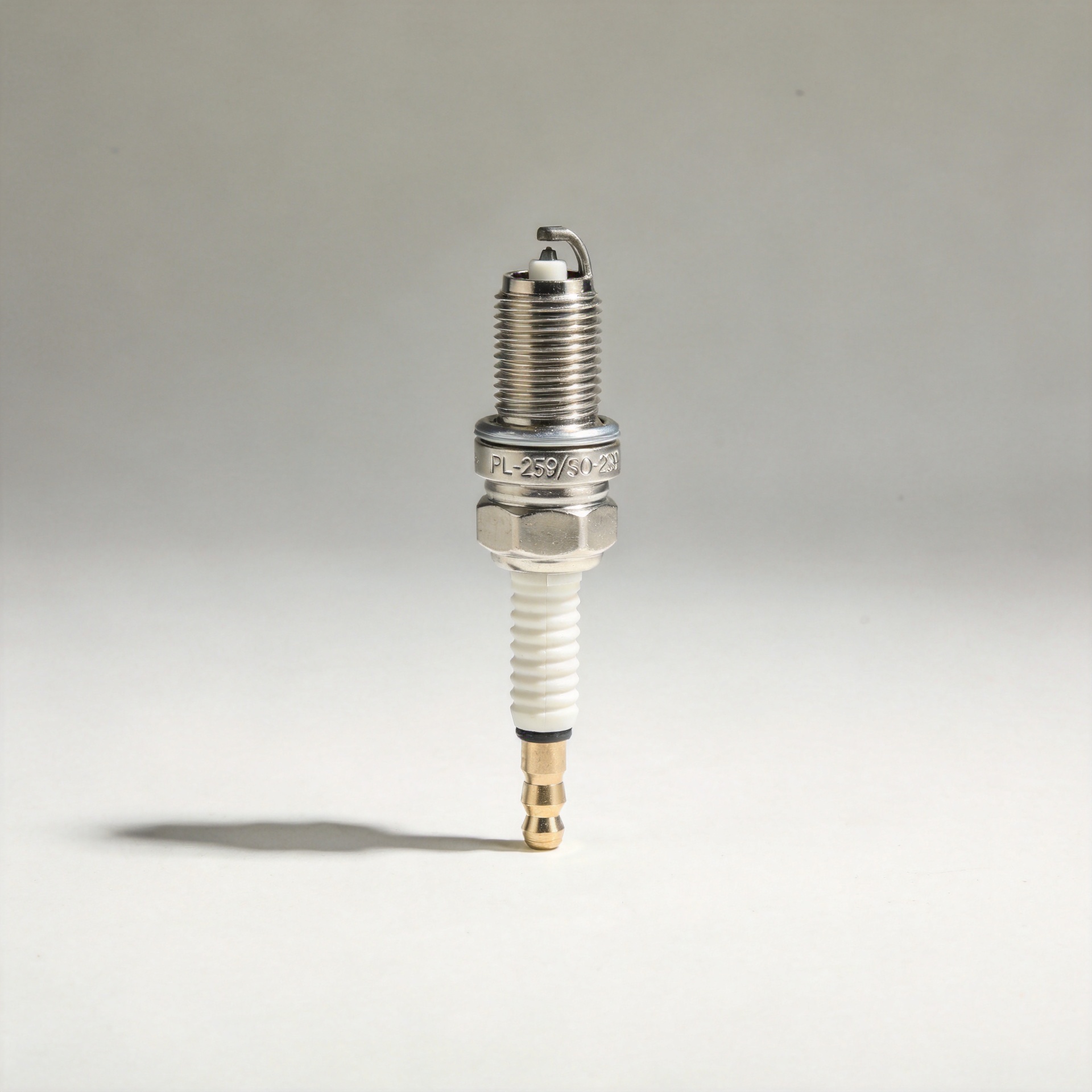
UHF Connector (PL-259/SO-239): Guide and Applications
As an RF systems engineer who has worked across base station installations, security infrastructure, and industrial automation projects, I've learned that connector selection often determines whether a signal chain performs to spec—or quietly degrades over time. The UHF connector, known by its military designations PL-259 (plug) and SO-239 (socket), is one of the most widely recognized coaxial connectors in the field, yet also one of the most frequently misspecified. Before choosing a UHF connector for your next installation, ask yourself: does your application actually fall within this connector's practical operating range?
This guide covers what UHF connectors are, how they compare to SMA, N-type, BNC, and TNC alternatives, and how to select the right interface for industrial, commercial, and communications deployments.
What Is a UHF Connector?
The UHF connector was designed in the 1930s for early radio applications. At the time, "UHF" referred to any frequency above 30 MHz—a definition long since superseded. Today's ITU and IEEE designations place the UHF band at 300 MHz to 3 GHz, well above where the PL-259/SO-239 UHF connector performs reliably. The name is a historical artifact that causes specification errors among buyers who assume the connector suits modern UHF-band work.
The connector features a 5/8 inch 24tpi UNEF threaded coupling shell, a nominal 50 Ω line impedance, and a maximum voltage rating of approximately 500 V peak. Some variants handle over 1 kW of RF power, making the UHF connector a practical choice for high-power HF transmitter outputs where power capacity matters more than upper frequency headroom.
That said, the SO-239 female has a non-constant surge impedance—there is a discontinuity of roughly 35 Ω from the standard 50 Ω line at the center pin transition. Above approximately 100 MHz, this creates measurable signal reflections and elevated VSWR. For systems operating below 100 MHz—CB radio, HF amateur radio, low-frequency communications—this tradeoff is generally manageable. Above that threshold, other connector types should be seriously evaluated.

UHF Connector Variants: Mini UHF
The standard PL-259/SO-239 form factor suits full-sized equipment and larger coaxial cable. In compact and handheld applications, the mini UHF connector provides a smaller-profile alternative that maintains the same basic threaded coaxial interface architecture. A mini uhf male connector sees common use in cellular repeater equipment, handheld radios, and compact antenna interfaces where the standard PL-259 body is too large for the housing.
When sourcing mini UHF components, verify impedance and frequency specifications against your actual application requirements. The same historical labeling issue applies: confirm the working frequency range before assuming the "UHF" label implies suitability for 300 MHz–3 GHz operation.
Connector Comparison: UHF vs. SMA, N-Type, BNC, and TNC
The choice between UHF and other connector types is primarily driven by frequency range and power handling. Here is how the major connector families compare:
| Connector Type | Typical Frequency Range | Impedance | Power Handling | Primary Use Cases |
|---|---|---|---|---|
| UHF (PL-259/SO-239) | DC–100 MHz practical | Non-constant (≈50 Ω) | High (1 kW+) | HF amateur radio, CB radio, high-power low-frequency transmitters |
| N-Type | DC–11 GHz | 50 Ω or 75 Ω | Medium-High | Base stations, outdoor antenna systems, instrumentation |
| BNC | DC–4 GHz | 50 Ω or 75 Ω | Medium | Test equipment, video, security cameras, low-frequency RF |
| TNC | DC–11 GHz | 50 Ω | Medium | Mobile communications, outdoor installations requiring vibration resistance |
| SMA | DC–18 GHz | 50 Ω | Low-Medium | Microwave, wireless modules, test ports, compact RF assemblies |
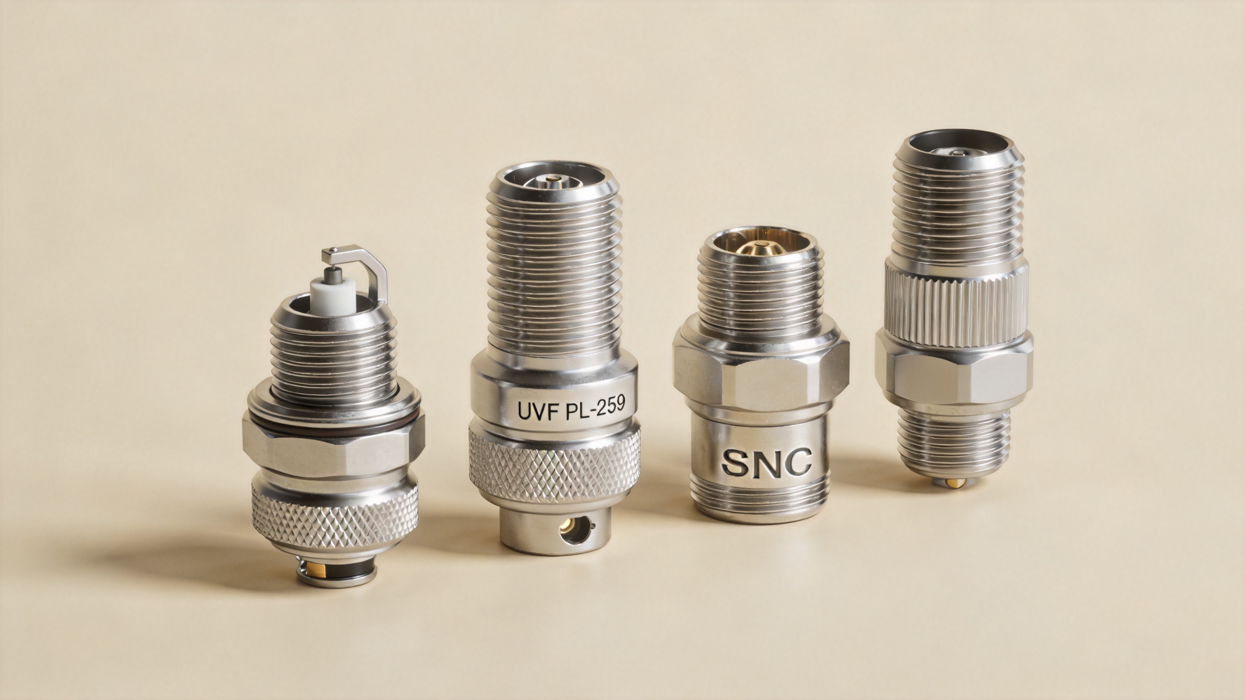
If your primary constraint is power handling at low frequencies (below 100 MHz), the UHF connector is a defensible choice with a well-documented track record. If your system operates above 100 MHz—whether that is security camera backbone infrastructure running over an RG6 F connector distribution system, or industrial wireless communications at VHF and above—N-type, BNC, or TNC interfaces will deliver more consistent signal integrity.
I initially assumed the same UHF connector selection logic applied equally to a 30 MHz HF link and a 450 MHz industrial monitoring radio. What actually happened was that elevated VSWR readings on the VHF system traced directly back to the impedance discontinuity in the SO-239 housing—a constraint the UHF connector was not originally designed to address.
Applications: Where UHF Connectors Are Used
The UHF connector remains the standard interface in several well-defined application areas:
- Amateur and CB radio: PL-259/SO-239 is the de facto standard on HF transceivers, mobile CB radios, and full-sized equipment operating below the connector's effective frequency ceiling.
- High-power transmitter outputs: The threaded coupling and generous contact cross-section suit amplifier outputs where power handling matters more than upper frequency precision.
- Security and CCTV systems: UHF connectors appear in backbone distribution boxes for legacy coaxial CCTV infrastructure, though BNC is more common at the camera-level interface.
- Industrial HF communications: Fixed-frequency HF radio systems in industrial automation, SCADA networks, and remote monitoring that operate below 30 MHz benefit from the UHF connector's power handling and mechanical durability.
Procurement Selection Criteria
When sourcing UHF connectors for B2B procurement, these parameters are worth verifying before placing an order:
- Working frequency: Confirm the signal path stays below 100 MHz where UHF connector performance is predictable. If any part of the system is close to or above that threshold, reconsider the interface type.
- Impedance consistency: A quick VSWR check at the upper end of your operating frequency range will tell you whether the connector sample stays within your link budget.
- Housing material and plating: Nickel-plated zinc alloy is cost-effective for indoor use. For outdoor or corrosion-exposed installations, verify the plating grade and consider brass or silver-plated options instead.
- Thread quality: The 5/8-24 UNEF thread should engage without binding. Inconsistent threading in lower-quality product can cause intermittent contact under vibration—a failure mode that typically surfaces weeks into service rather than at installation time.
- Certification: For installations in European markets or regulated environments, confirm CE marking and RoHS compliance documentation before placing the order.
Worldpeak produces the UHF-BASIC-02 UHF (PL259) Female Connector, a nickel-plated zinc alloy SO-239 at 50 Ω with CE certification and standard thread. For high-power applications, the RFX-Custom-02 High-Power RF Connector (7/16 DIN Female to N Male) is rated to 3 kW at 2.5 GHz. For applications that need N-type at higher frequencies—up to 6 GHz—the RF-N-75B Low-PIM N Connector is appropriate for cable television, DAS, and precision measurement work.
Installation and Signal Loss Prevention
In practice, most signal loss in UHF connector installations comes from assembly quality rather than the connector itself. Under-torqued mating is a common culprit: the problem often does not surface immediately, but appears after thermal cycling or vibration. At that point, finding the cause requires sweeping every connection in the chain.
- Match the cable reducer to the cable diameter. PL-259 connectors are available with reducers for RG-58 and RG-59; using the wrong reducer—or no reducer—creates a mechanical gap that produces intermittent contact.
- Verify the center pin solder joint before threading the outer shell. A cold or incomplete joint at the center pin is a frequent source of intermittent RF contact.
- After installation, a VSWR check at operating frequency is the most reliable way to confirm connection integrity. If a standing-wave pattern appears that was not there before, start at the connector interfaces before checking the cable run itself.
- For any outdoor UHF connector, weatherproofing tape over the completed joint blocks moisture ingress at the cable-connector interface—where corrosion-driven degradation most often begins.
Conclusion
The UHF connector (PL-259/SO-239) is a well-proven choice for HF and low-frequency applications where power handling and mechanical reliability are the primary requirements. If your operating frequency stays below 100 MHz and the application suits the standard threaded interface, this connector has a long track record supporting that use. For work above 100 MHz—or where constant 50 Ω impedance is required throughout the signal path—N-type, BNC, or TNC connectors are better suited. Whatever the interface, verifying working frequency, housing material, thread quality, and certification requirements before finalizing the specification is the single most effective way to avoid specification mismatches that only show up after installation.





