 EN
EN

What Are the Key Specs of Low Loss Feeder Cable?
Early in my work with antenna feed systems, I optimized cable selection around a single parameter: insertion loss per meter. The blind spot was that low-loss feeder cable performance depends on at least five interdependent specifications simultaneously, and optimizing for attenuation alone can leave power handling, shielding, or weatherproofing inadequate for the actual installation environment. If you are specifying a low loss feeder cable for a base station, distributed antenna system (DAS), or outdoor microwave link, this breakdown covers the specifications that matter most and how they interact in practice.
1. Characteristic Impedance: The Non-Negotiable Foundation
All telecom-grade feeder cable is specified at 50 ohms characteristic impedance. This is not arbitrary: 50 ohms represents a practical compromise between minimum attenuation (which would favor approximately 77 ohms) and maximum power handling (which favors approximately 30 ohms). Matching the feeder cable impedance to the transceiver, antenna, and any in-line components is what prevents reflected power and standing wave build-up from degrading your link budget. Before evaluating any other specification, confirm that every element in the feeder path shares this 50-ohm reference.
2. Attenuation Per Unit Length: The Primary Loss Specification
Attenuation is the specification that most procurement teams focus on first, and rightly so. It sets the maximum usable feeder length for a given frequency and link budget. However, the datasheet attenuation figure is a lower bound, not a field guarantee — connector mating angles, installation geometry, and temperature variation all add incremental loss that the benchtop measurement does not capture.
A useful comparison across commonly used cable types at 2.4 GHz:
| Cable Type | OD (inches) | Attenuation @ 2.4 GHz | Construction |
|---|---|---|---|
| RG-214/U (rg214 cable) | 0.425" | ~0.67 dB/m | Double braid, solid PE dielectric |
| LMR-400 | 0.405" | 0.223 dB/m | Foam dielectric, double shield |
| lmr600 cable (LMR-600) | 0.590" | 0.144 dB/m | Foam dielectric, double shield |
| 7/8" corrugated hardline | 0.55" | ~0.062 dB/m (est.) | Corrugated copper outer, foam PE |
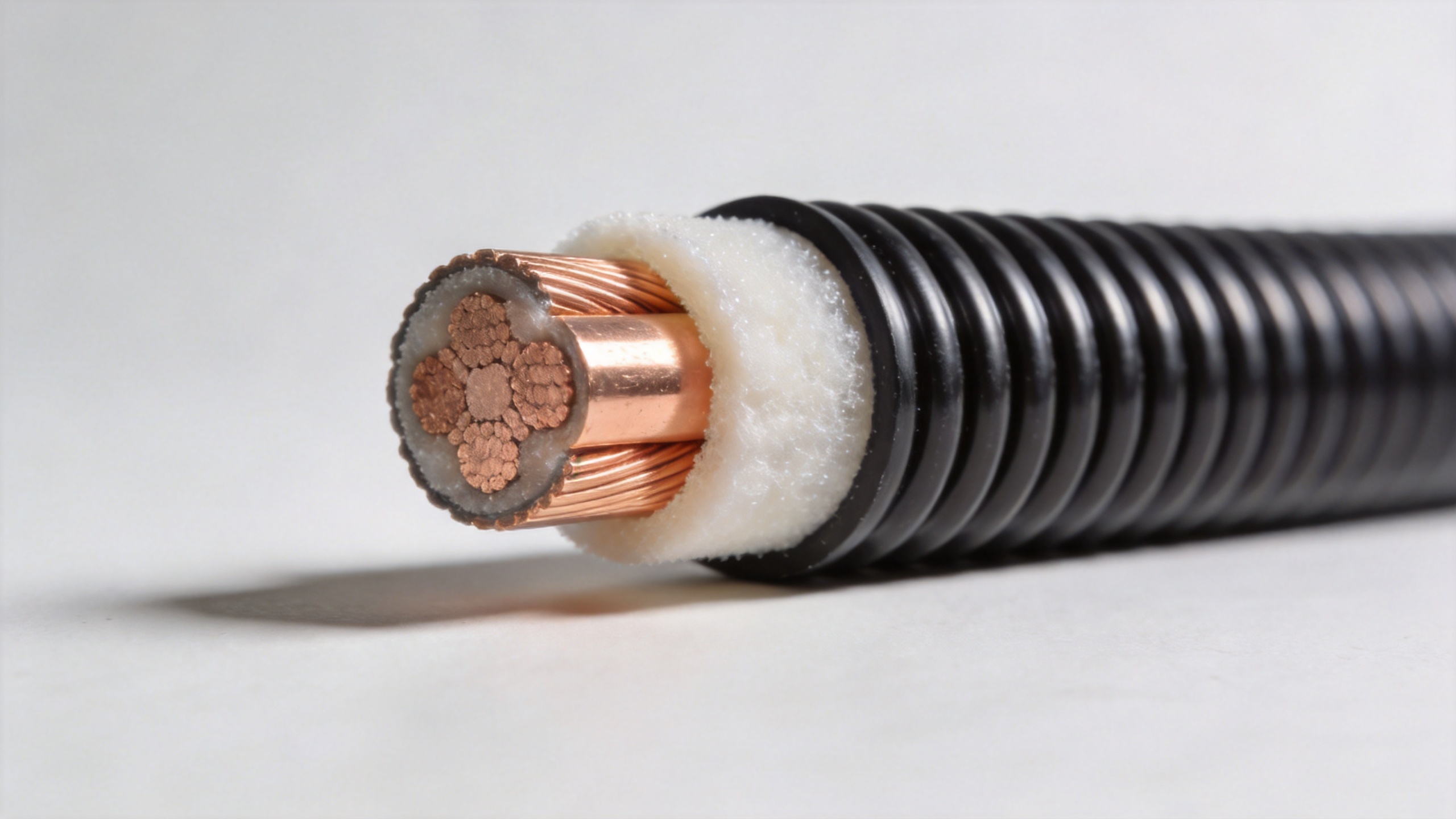
The contrast between the rg214 cable and modern foam-dielectric LMR-series cable is significant: LMR-400 achieves roughly three times lower loss at 2.4 GHz in a nearly identical physical diameter. For feeder runs longer than 15–20 meters, this difference has a measurable impact on link margin. The lmr600 cable provides a further reduction — roughly 35% lower than LMR-400 at 2.4 GHz — in a larger 0.590-inch diameter. Corrugated hardline delivers the lowest attenuation of the group, with the trade-off being installation flexibility, discussed in Section 5.
3. Dielectric Type and Its Effect on Loss and Power Handling
The dielectric material between inner and outer conductors is what separates modern low loss feeder cable from older solid-PE designs. Low-density foam dielectric reduces both capacitive loss and dielectric heating, enabling lower attenuation and higher continuous power handling in the same physical diameter. If the installation environment stays within the cable's rated temperature range and the foam structure is mechanically intact, you should see performance close to the datasheet figure. Once the foam dielectric is compressed by over-bending or damaged by moisture ingress, attenuation increases — often without visible external indication.
For outdoor feeder applications where moisture is a long-term risk, PTFE dielectric offers better moisture resistance than foam PE, though at higher cost and typically higher loss per unit length. LSZH jacket options address fire safety requirements for in-building DAS installations.
4. Power Handling: Often Under-Specified
A specification category that gets skipped more often than it should is power handling. Teams selecting a low loss feeder cable sometimes anchor entirely on frequency range and attenuation, leaving power handling out of the RFQ entirely. In high-power base station transmit chains and 5G NR deployments, this omission can result in connector and dielectric thermal failure under continuous operation. Power handling rating depends on both cable diameter and dielectric type, and it degrades with increasing frequency because of the higher RF current density in the conductor surfaces.
It is tempting to select a cable based on lowest insertion loss, and for most bench applications that approach works. For an outdoor base station feeder with a high-power amplifier at the back end, I would look carefully at the peak power and average power ratings before finalizing the cable diameter selection. Roughly speaking, doubling cable diameter approximately doubles the continuous power handling capability, which is one reason 7/8-inch corrugated cable remains the preferred choice for high-power macro-cell feeders despite its installation complexity.
5. Shielding Effectiveness: Critical for DAS and In-Building Applications
Shielding effectiveness determines how effectively the cable isolates the transmitted signal from the surrounding electromagnetic environment. In base station tower installations, shielding prevents radiated interference from coupling into adjacent cable runs. In distributed antenna systems inside buildings, it prevents co-channel interference between sectors and eliminates passive intermodulation (PIM) contributions from the feeder path itself.
Modern low loss feeder cable uses a combination of foil and braid shields, typically providing 85 dB or better shielding effectiveness in the telecom frequency range. For multi-carrier in-building DAS, the cable and connector interfaces must both be PIM-rated — a specification that the shielding effectiveness figure alone does not capture.
6. Weather Protection and Jacket Specifications for Outdoor Installation
A post-installation review I have seen repeated across multiple outdoor antenna projects is that the cable and connector interface weatherproofing receives less attention than the cable's electrical specifications — and it is the weatherproofing that determines whether the installed assembly performs to spec through its second and third year of outdoor service.
Key jacket specifications for outdoor low loss feeder cable include UV stabilization, operating temperature range (typically −40°C to +85°C for telecom-grade products), and jacket material compatibility with the installation environment. Installations in coastal, industrial, or high-pollution environments benefit from jacket compounds that resist oil, ozone, and airborne contaminants beyond what a standard PE jacket tolerates. Connector interfaces should be sealed with manufacturer-specified weatherproofing tape or pre-applied sealant to prevent moisture wicking along the cable-connector transition.
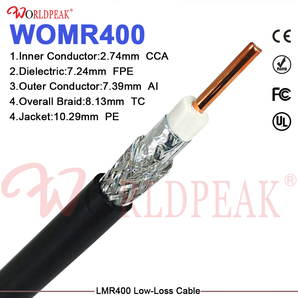
For applications requiring custom feeder lengths, non-standard connector combinations, or specific jacket specifications for unusual climate conditions, factory-assembled and tested feeder cable assemblies simplify site logistics and ensure connector interface integrity before the cable leaves the facility. The LMR400 Low-Loss 50 Ohm Coaxial Cable offers a practical balance between flexible handling in shorter feeder runs and the low-loss performance requirements of modern telecom infrastructure.
7. Connector Compatibility and the Role of RP-SMA in Feeder Systems
Feeder cable selection is only half of the signal path equation — connector compatibility at both ends determines the actual insertion loss, mechanical integrity, and weatherproofing of the complete assembly. N-type connectors are standard for most telecom feeder applications due to their better weatherproofing performance and higher power handling relative to SMA. The rp sma cable configuration — using reverse-polarity SMA connectors — appears in specific in-building wireless and WLAN applications where regulatory requirements mandate the non-standard gender interface to limit end-user modification. Understanding which connector type is specified at each interface point before ordering feeder assemblies avoids the integration delays that result from gender and polarity mismatches discovered on site.
Practical Reference: Matching Cable Specs to Application
- Short in-building DAS runs (under 10 m): LMR-400-class flexible cable provides adequate loss performance with manageable installation effort; verify PIM rating if the system carries multiple carriers.
- Medium outdoor runs (10–30 m) at sub-6 GHz: LMR-600-class cable reduces feeder loss contribution to the link budget without requiring the installation tools and bending constraints of hardline.
- Long feeder runs on high towers or high-power sites: 7/8-inch or 1-5/8-inch corrugated hardline provides the lowest available loss at the cost of installation flexibility; requires proper weatherproofing at every connector interface.
- Legacy RG-214 replacement: LMR-400-class cable in a similar physical diameter achieves approximately three times lower attenuation and improved power handling, making it the practical upgrade choice for modernization projects.
Specifying low loss feeder cable is a five-variable problem, not a one-variable lookup. Cable diameter drives attenuation and power handling simultaneously. Dielectric type drives loss, moisture resistance, and operating temperature range together. Jacket material determines long-term outdoor service life in ways the electrical specs say nothing about. Getting all five matched to the installation context is what determines whether the system holds its link margin through year three — or starts requiring maintenance visits that cost more than the cable ever did.





