 EN
EN

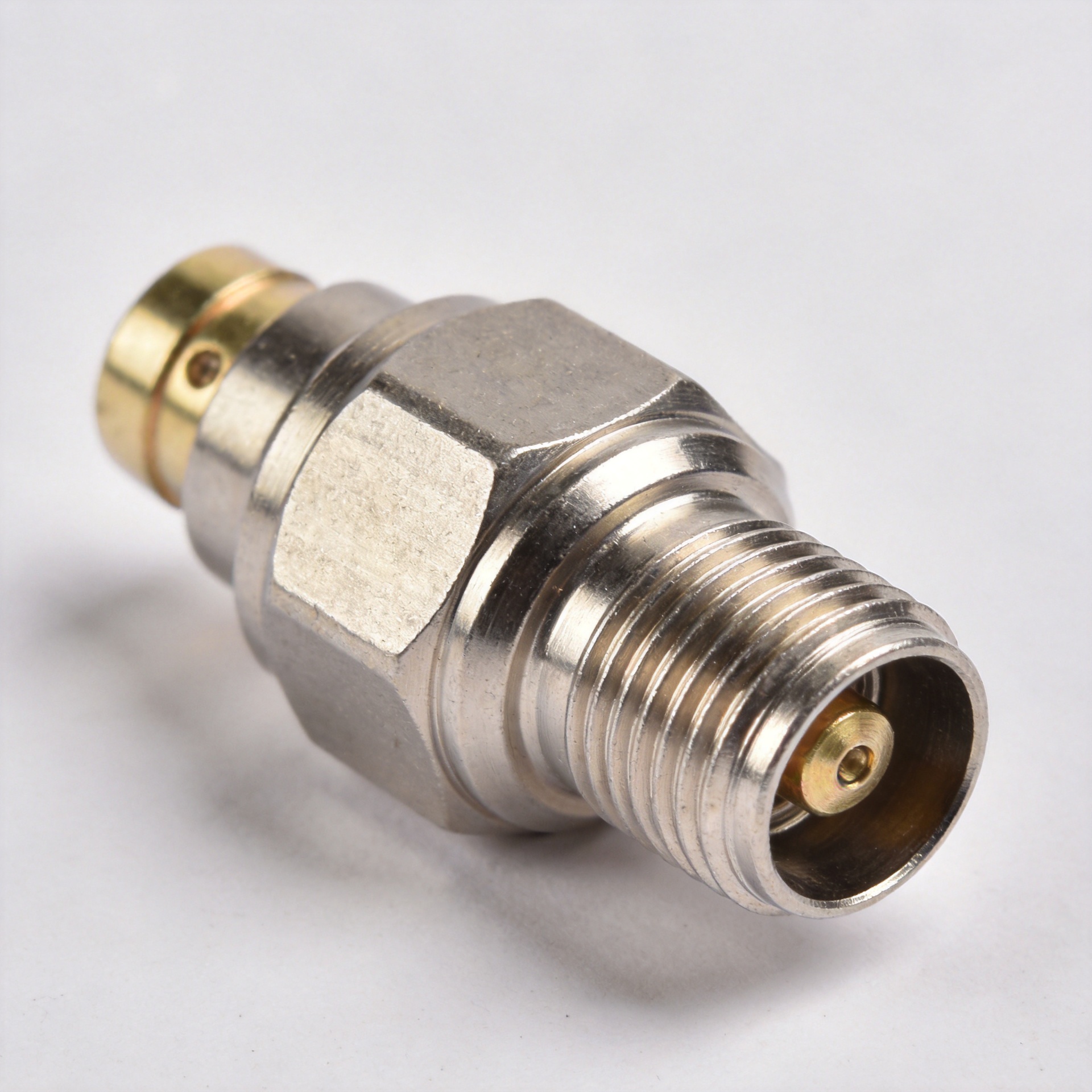
A heavy-duty n type connector is a threaded, weather-resistant coaxial interface engineered for applications where robust physical retention, environmental sealing, and repeatable high-frequency electrical performance are required. Commonly deployed across cellular base stations, outdoor wireless bridges, antenna feed systems, and precision test benches, the performance of an n type connector dictates overall link budget stability.
System designers must evaluate impedance alignment, operating frequency margin, continuous-wave power capacity, and cable termination mechanical limits prior to specifying catalog hardware.
Mechanical Configuration and Impedance Standards
The foundational architecture of an n type connector incorporates a robust threaded coupling mechanism, a central contact pin, dielectric insulation, and an outer conductor interface. The threaded design provides superior resistance to axial strain and continuous vibration compared to bayonet-style couplers, making it an ideal candidate for harsh outdoor deployments.
According to IEC 61169-16 standards, N-type interfaces are manufactured in both 50-ohm and 75-ohm characteristic impedance variants:
-
50-Ohm Systems: Standard for cellular telecommunications, microwave links, Wi-Fi infrastructure, and RF lab instruments.
-
75-Ohm Systems: Specialized for high-definition video transmission, CATV distribution, and broadcast infrastructure.
Intermating 50-ohm and 75-ohm interfaces causes physical damage to center contacts due to differing pin pin-diameter dimensions, while creating severe impedance discontinuities that spike Voltage Standing Wave Ratio (VSWR).
Interface Geometries and Structural Considerations
Straight Plugs and Panel Mount Receptacles
A standard type n male connector features an internal coupling nut paired with a center male contact pin. Mating female receptacles carry outer threading and a recessed pin socket. In field equipment enclosures, panel-mount female receptacles function as primary bulkhead interfaces.
To ensure long-term physical reliability, panel-mount installations require proper chassis cutout dimensions, resilient O-ring sealing gaskets, and strict torque limits during mounting to protect internal solder terminations.
Right-Angle Interfaces and Spatial Routing
Deploying a right angle n type connector solves severe spatial constraints inside tight enclosures or cabinet walls where straight cable exits would violate minimum bend radius guidelines. However, internal right-angle corner geometries introduce potential impedance discontinuities.
For high-frequency microwave paths, selecting precision-machined right angle n type connector assemblies with swept internal conductors minimizes insertion loss spikes and preserves return loss headroom across operating frequencies.
In-Line Adapters and Barrel Assemblies
A double-female n type barrel connector provides a direct mechanism for joining two male-terminated coaxial cable runs or extending panel test access. Every barrel interface adds two mechanical contact points into the signal path. Therefore, verifying center pin plating thickness, thread tolerances, and dielectric alignment on an n type barrel connector prevents cumulative insertion loss accumulation.
Comparative Analysis of Standard Threaded and Bayonet Interfaces
Selecting the optimal connector family requires balancing spatial footprint against mechanical strain resistance and environmental shielding.
| Interface Standard | Coupling Mechanism | Primary System Strengths | Application Limitations |
| N-Type | Medium Threaded | High power, rugged outdoor protection, broad 50/75-ohm availability | Larger spatial footprint than miniature series |
| TNC | Small Threaded | Compact footprint with vibration-resistant threaded retention | Lower maximum RF power handling capacity |
| BNC | Bayonet Lock | Rapid connect/disconnect mechanism for test benches | Unsuitable for high-vibration or outdoor feeder runs |
Where mechanical durability, high RF power transmission, and weatherproofing take precedence over spatial footprint, an n type connector remains the premier industry choice.
RF Power Handling and Impedance Matching Dynamics
In high-power broadcast and cellular transmitter paths, an n type connector functions as a thermal and voltage bottleneck. Power handling capability decreases significantly as operating frequency, ambient temperature, and altitude increase due to dielectric thermal stress and voltage breakdown limits.
| Operating Parameter | Thermal & Electrical Risk | Engineering Mitigation Strategy |
| High Operating Frequency | Increased skin-effect heating on center pin | Select low-loss dielectric materials and silver-plated pins |
| Elevated Ambient Temp | Reduced heat dissipation capacity | Apply power derating factors from factory curves |
| Impedance Mismatch | High VSWR causes localized voltage peaks | Match cable assembly impedance to 50 ohms across the path |
| Excessive Vibration | Thread loosening causes contact arcing | Apply calibrated mating torque using precision tools |
Matching the type n male connector to the exact coaxial cable dimensions—utilizing appropriate crimp, clamp, or solder attachment methods—guarantees stable mechanical retention and continuous 50-ohm impedance matching.
Outdoor Weatherproofing and Environmental Sealing
While the threaded body of an n type connector offers moderate moisture resistance, outdoor tower and rooftop installations require secondary environmental protection. Water entering through unsealed rear crimp ferrule sleeves or un-gasketed bulkhead threads corrodes the copper braid, causing rapid signal degradation.
Effective weatherproofing combines proper mechanical torqueing, high-density butyl rubber sealing wrap, and an outer layer of UV-resistant vinyl tape. Additionally, securing heavy feeder lines with cable cleats prevents mechanical tension from pulling directly on the type n male connector interface.
System Integration Procurement Checklist
When sourcing high-frequency N-type components for volume integration, technical specifications must state:
-
Nominal system impedance (50-ohm vs 75-ohm architecture).
-
Target frequency range, maximum allowable insertion loss, and VSWR limits.
-
Body geometry (straight, panel-mount, bulkhead, or right angle n type connector).
-
Cable termination style (crimp, clamp, solder, or captive center pin).
-
Coupling nut torque callouts and body material specifications (brass, stainless steel, or tri-metal plating).
-
Necessity of inline adapters, such as a precision n type barrel connector for extended bench testing.
-
Factory inspection standards, including 100% vector network analyzer (VNA) swept-frequency acceptance data.
Precision Manufacturing and Global Supply Capabilities
Delivering high-reliability interconnects for modern RF systems demands high-precision CNC machining, strict plating quality controls, and advanced RF testing. Worldpeak is an established manufacturer of high-performance RF connectors, adapters, and custom cable assemblies serving global telecommunications, defense, and industrial automation markets.
Utilizing automated production technology and advanced vector network analyzers (VNAs), Worldpeak manufactures standard and custom n type connector products designed for low VSWR, superior Passive Intermodulation (PIM) performance, and long-term mechanical reliability. Through rigorous raw material inspection, lot traceability, and flexible OEM manufacturing capabilities, Worldpeak supports global system integrators with scalable, high-precision interconnect solutions built for demanding operating conditions.





