EN
EN

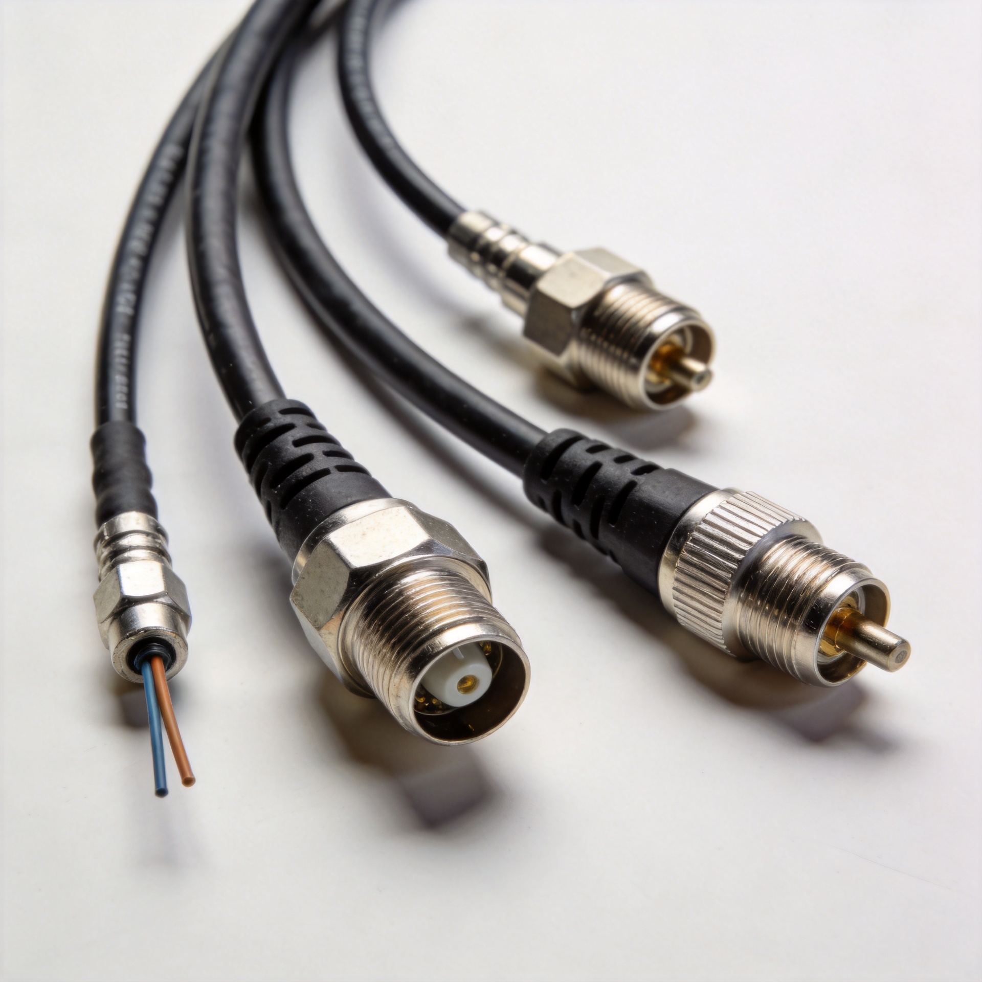
How OEM RF Cable Customization Solves Low Signal Transmission Challenges
When a wireless link loses margin, the first suspect is often the radio or antenna. In practice, the RF cable assembly between them can be where a workable design becomes a marginal one. Having sourced RF components for telecom projects, I have learned that lead time and price matter, but repeatable electrical performance across batches matters just as much. OEM customization makes it possible to define the whole signal path—cable, connectors, length, shielding, termination, and documentation—as one controlled assembly.
A low loss RF cable is not simply a thicker cable with a better label. Loss depends on frequency, conductor and dielectric construction, length, connector interfaces, bends, and the way the cable is installed. Customizing those variables around the actual application can protect link budget without adding unnecessary size, cost, or assembly work.
Why a Standard RF Cable Can Leave a Signal Margin Problem Unsolved
Off-the-shelf assemblies are useful when frequency, routing, connector family, and environment are already known. The trouble starts when one of those assumptions is wrong. A cable that is adequate on a short bench run may create meaningful attenuation on a longer outdoor run at a higher operating frequency. A connector that mates mechanically may still introduce a mismatch if its impedance, interface quality, or torque practice is not controlled.
That distinction is important because attenuation is frequency dependent. Comparative coax references show that 50-ohm cable constructions can have very different loss values at the same frequency, and the gap grows as frequency rises. The exact number must come from the selected cable manufacturer’s data at the project frequency and length; still, the design lesson is clear: specify the complete RF cable path, not just a generic cable category.
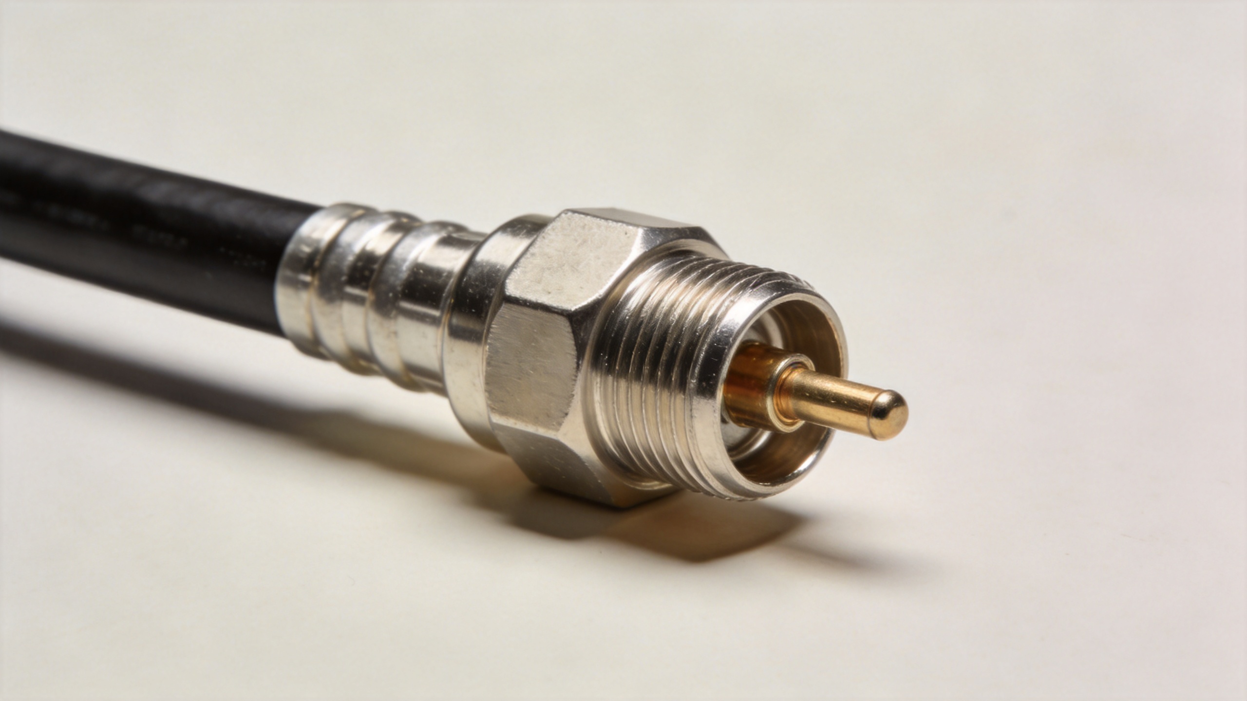
Start With the Real Signal Path
Consider a typical remote radio or antenna installation. The RF signal leaves the equipment port, crosses one connector interface, travels through a routed cable, passes another connector, and reaches the antenna or front-end device. Every transition can consume margin. The most effective OEM approach is to map that path before selecting part numbers.
- Frequency band and bandwidth: Set the upper operating frequency and any phase or amplitude stability needs.
- System impedance: Match the assembly to the system impedance, commonly 50 ohms for RF and microwave equipment, instead of mixing interfaces by convenience.
- Installed length: Include service loops and routing allowances, not only the straight-line distance.
- Connector interfaces: Define both ends, gender, coupling style, panel clearance, and mating cycle expectations.
- Environment: Account for UV exposure, moisture, temperature swing, abrasion, vibration, and required bend radius.
This is where low loss RF cables become a system decision. A lower-loss construction may be appropriate for a long high-frequency run, while a more flexible option may be the better trade-off inside a compact enclosure. Actually, low loss is only one part of a reliable assembly; an unsuitable jacket or poorly controlled termination can undo the benefit.
What OEM Customization Changes
1. Cable construction is matched to the electrical target
An OEM supplier can propose cable families after the frequency, maximum length, routing constraints, and loss budget are known. For example, a semi-rigid construction can support repeatable geometry where phase stability and shielding are priorities, while a flexible coax may better suit a moving or tight-routing application. The point is not to claim one construction suits every case. It is to make the choice traceable to a measured requirement.
2. Connector selection is treated as part of the RF cable
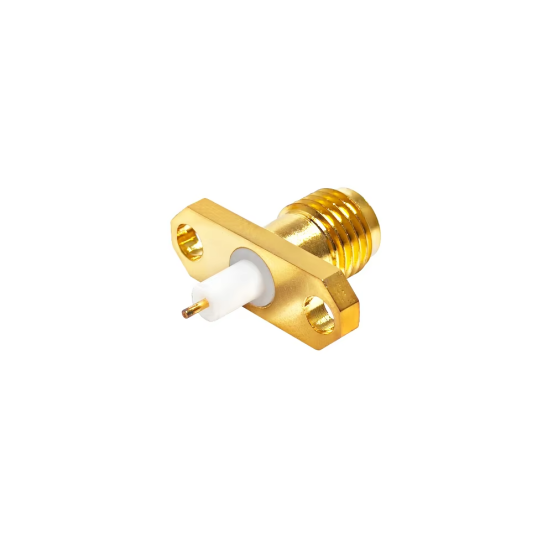
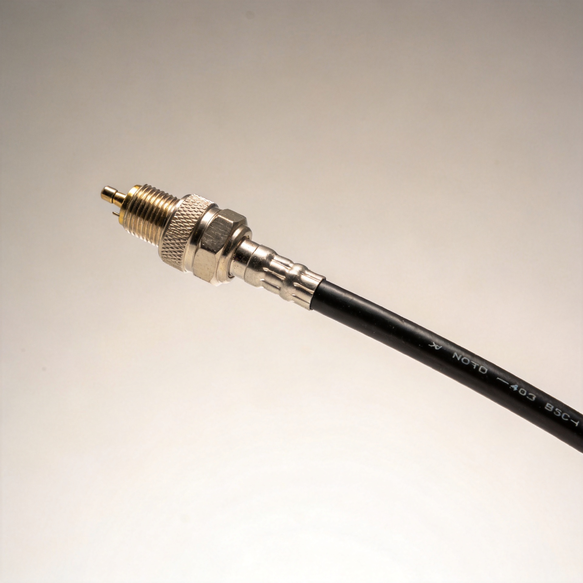
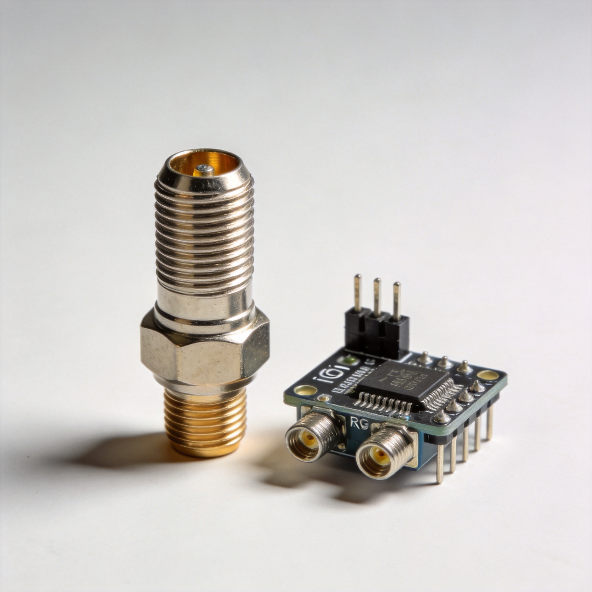
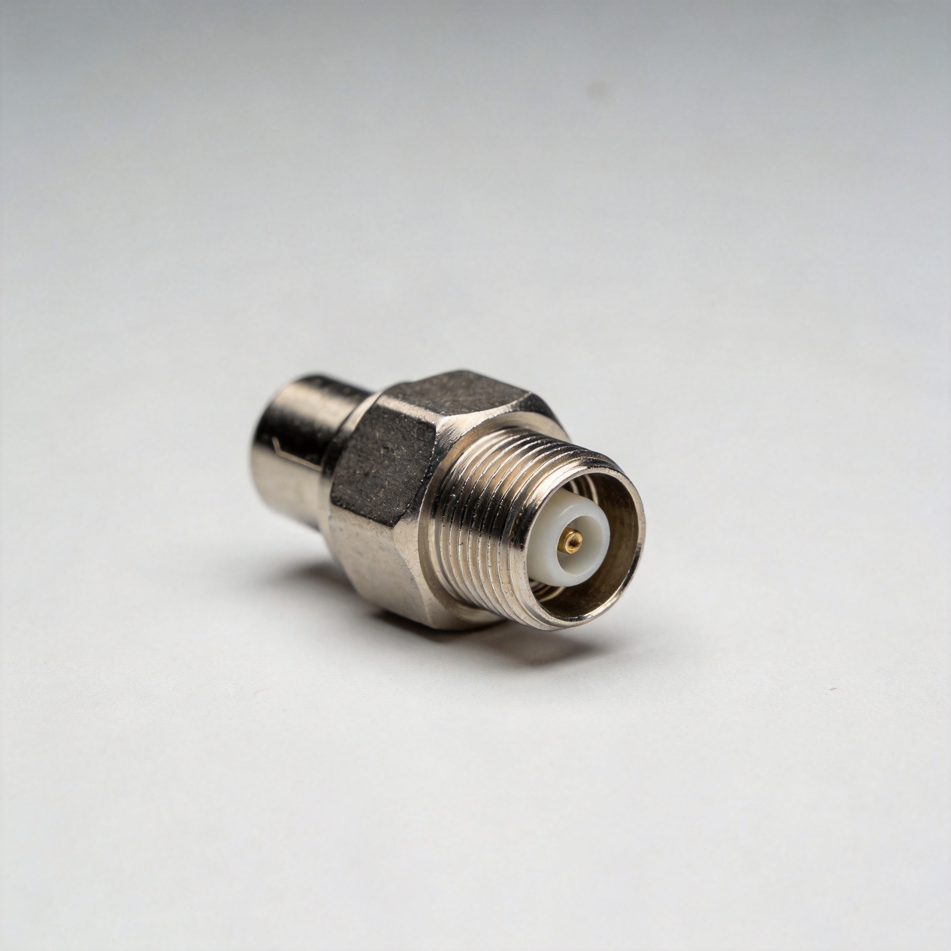
Connector choice affects more than physical fit. The interface must support the operating frequency, impedance, power level, installation space, and sealing needs. An OEM assembly can combine the requested cable with interfaces such as SMA, N-type, BNC, TNC, or other standard formats where the application requires them. The connector-to-cable termination process should be controlled so the transition does not become an unplanned reflection point.
3. Length and routing are controlled before installation
Custom cut length avoids the common field workaround of coiling excess cable or stretching a run beyond its intended route. Both can complicate installation and repeatability. For a high-frequency RF cable, document the final length tolerance, minimum bend radius, strain-relief position, and labeling so the installation team can reproduce the intended path.
4. Environmental protection is designed into the assembly
Outdoor signal problems may stem from more than attenuation. Moisture ingress at connector interfaces and unsuitable sealing arrangements can appear after weather exposure. For an outdoor assembly, specify the jacket material, connector sealing method, boot or heat-shrink requirements, and installation guidance together. A procurement decision that looks cheaper at unit level can become expensive after field replacement, travel, and degraded service are counted.
Specify Validation, Not Just Parts
One useful change in procurement practice is to treat test documentation as part of the deliverable. Ask the supplier which checks apply to the assembly: continuity, insulation, VSWR or return loss where appropriate, insertion loss at agreed frequencies, visual workmanship, and dimensional or connector-interface checks. The exact acceptance limits should be agreed for the project rather than copied from a generic datasheet.
Worldpeak’s published site profile identifies RF connectors, adapters, antennas, and OEM RF solutions as its focus, with connector and cable-assembly production experience across standard interfaces from DC through 18 GHz. That breadth can help a buyer consolidate multi-interface sourcing, but the RFQ should still state the electrical and environmental requirements that govern the individual RF cable assembly.
A Practical OEM RF Cable RFQ Checklist
- State frequency range, impedance, power conditions, and target loss or return-loss criteria.
- Provide end-to-end length, allowed tolerance, route, bend-radius restriction, and installation environment.
- Identify both connector interfaces, mating hardware, and any panel or enclosure clearance limits.
- Specify cable-jacket, shielding, weatherproofing, labeling, and strain-relief needs.
- Request the applicable inspection and test records for pilot samples and production batches.
- Approve a sample assembly before scaling an order, especially when the design includes new terminations or a demanding environment.
Turn a Weak Link Into a Controlled Assembly
Low signal transmission rarely has one universal fix. The better response is to identify where loss, mismatch, ingress, or installation variability enters the path and remove those uncertainties through specification. OEM RF cable customization gives engineering and procurement teams a way to align cable type, connector transition, length, shielding, and validation around one application.
For buyers evaluating low loss RF cables, the final question is not “Which cable is lowest loss?” It is “Which documented assembly meets this frequency, route, environment, and interface requirement with repeatable production quality?” That is the question a well-prepared OEM RFQ can answer.