EN
EN

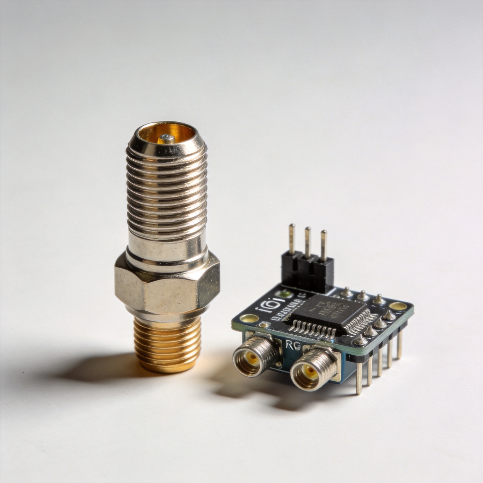
Why OEM Customized SMA Connector Fits Compact IoT Communication Hardware
When an IoT radio board moves from a bench prototype into a compact enclosure, the connector is no longer a small purchasing detail. The SMA connector affects antenna placement, cable routing, service access, sealing choices, and the repeatability of RF testing. For product teams building gateways, trackers, sensor nodes, radio modules, or edge devices, an OEM-customized SMA connector can turn a difficult mechanical compromise into a controlled design decision.
An SMA connector is a threaded, semi-precision coaxial RF interface commonly used in RF and microwave equipment. That threaded coupling is one reason it remains familiar to engineers: it gives a positive mechanical connection rather than relying on a push-on fit. Yet “SMA” alone does not define a finished design. The body style, mounting method, cable exit, center-contact option, material selection, and inspection plan all need to match the device around it.
Compact IoT hardware creates a connector problem, not just an RF problem
Small communication products often bring several constraints together. A radio board may sit close to a battery, display, metal chassis, sensor harness, or shield can. The antenna may be external, panel mounted, or routed through a short cable assembly. At the same time, the enclosure must be easy to assemble and durable enough for its intended environment. A standard catalog part can work, but its geometry may force an awkward cable bend or consume more clearance than the layout can spare.
This is where an OEM SMA connector specification becomes useful. Instead of starting with an arbitrary connector and adapting the device around it, the team can define the interface from the enclosure inward. That discussion can include bulkhead or board mounting, straight or right-angle cable exit, thread length, washer stack, cable length, strain-relief space, and the required mating side. The goal is not to make the connector special for its own sake. It is to avoid a collection of small integration workarounds that later complicate assembly and field service.
Why the threaded SMA format suits serviceable RF connections
Compact devices still need practical access to antennas, test fixtures, or replacement cable assemblies. A threaded sma rf connector gives technicians a familiar coupling action and a visible mechanical interface. In a device with an external antenna lead, this can be easier to manage than routing a delicate cable through an enclosure after final assembly.
The electrical target also belongs in the discussion. SMA connector families are generally used in 50-ohm RF systems, while frequency capability depends on the specific connector construction and the complete signal path. Some published SMA variants are specified to high microwave frequencies, but a product team should not treat a headline frequency as a blanket promise. Cable type, launch design, mating interface, bend radius, and assembly quality all influence the finished result. For IoT hardware, the relevant question is whether the complete assembly meets the radio band, loss, return-loss, and mechanical requirements that the product actually uses.

Customization points that matter in a tight enclosure
1. Mounting geometry and panel thickness
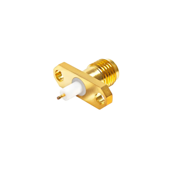
A bulkhead SMA connector must match the enclosure wall and the available nut-and-washer clearance. An OEM request can define the usable thread length, flats for anti-rotation features, and the outside profile so the connector remains reachable after the product is assembled. These details help prevent a situation where the RF port is electrically correct but impossible to torque or inspect.
2. Cable exit and routing
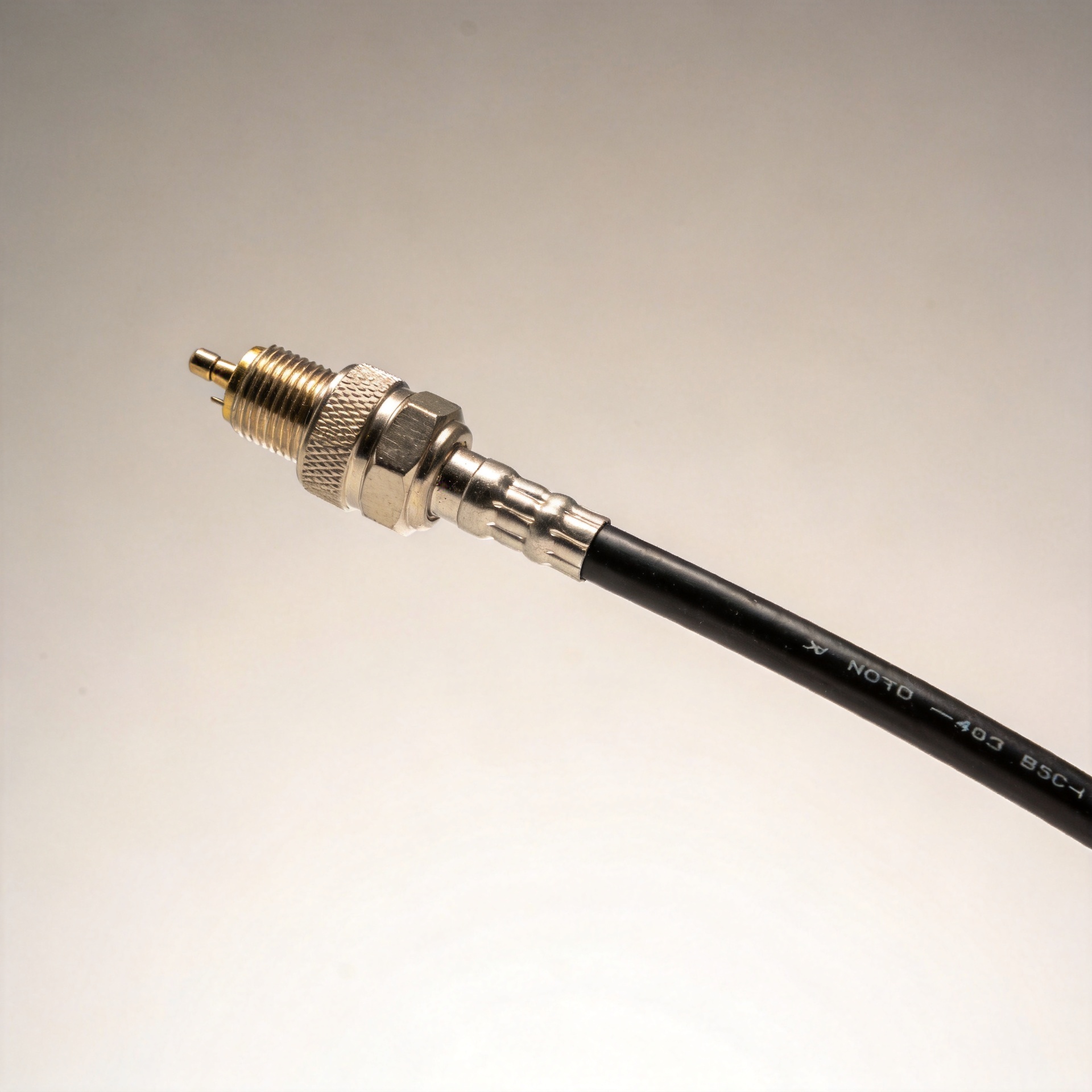
For a board-to-panel connection, a straight exit is not automatically the cleanest option. A right-angle or low-profile cable exit may reduce stress near the connector and preserve space above a PCB. The assembly drawing should state the cable route and the allowed bend area rather than asking production to infer it. This is especially helpful when the same enclosure supports several radio variants.
3. Interface definition and mating control
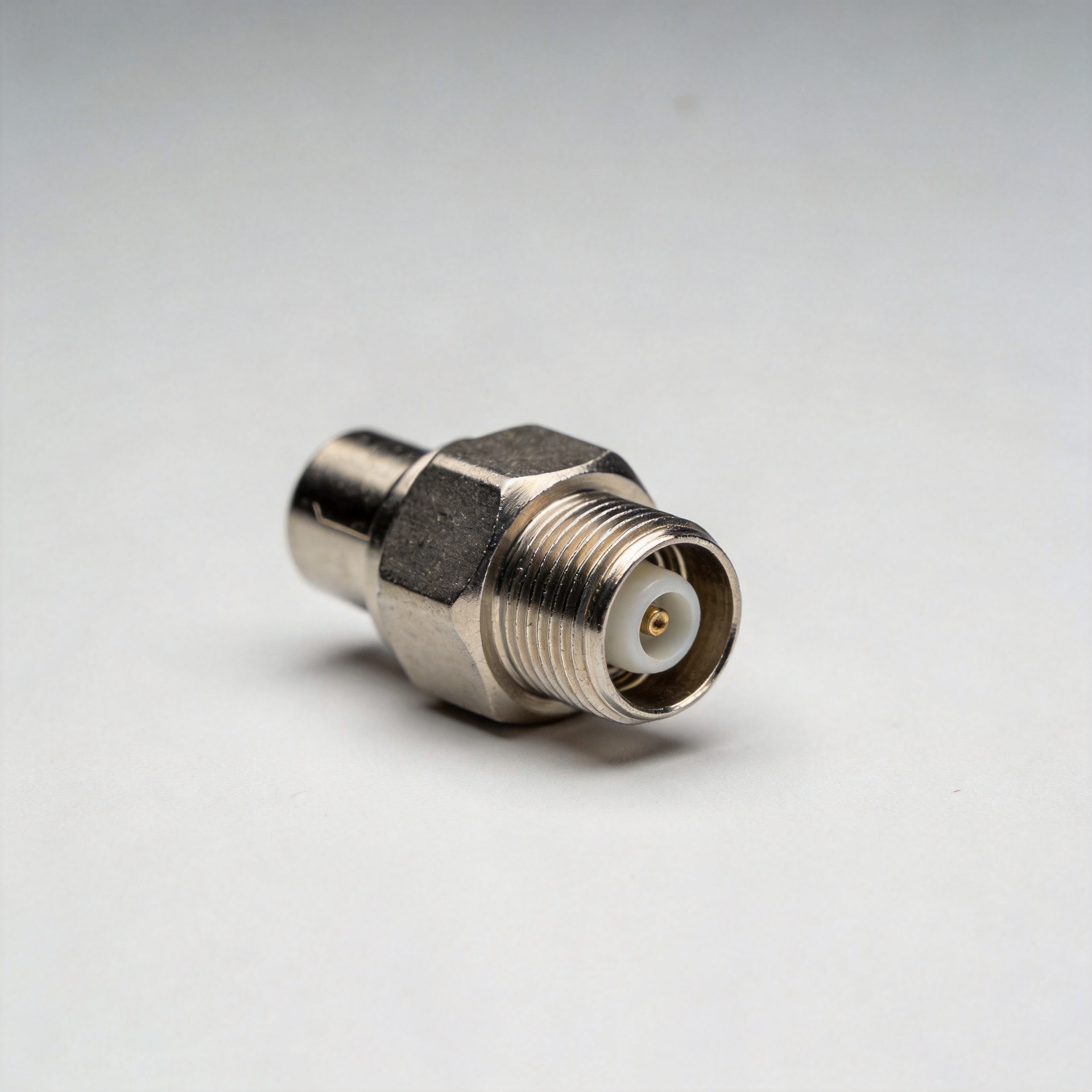
Engineers should state the desired gender and any polarity-specific requirement clearly. Names that sound similar can create expensive assembly errors. A controlled BOM, connector drawing, and mating-part reference help keep the antenna, cable, and device interface aligned. The sma rf connector should be reviewed as part of the complete mated pair, not as an isolated component.
4. Materials and finish for the intended environment
Material and plating choices should follow the environmental and reliability requirements of the device. A portable indoor sensor and an outdoor communications enclosure may need different corrosion, handling, or mating-cycle considerations. The right choice comes from the product specification and validation plan, not from a generic assumption about every SMA connector.
OEM coordination can reduce assembly variation
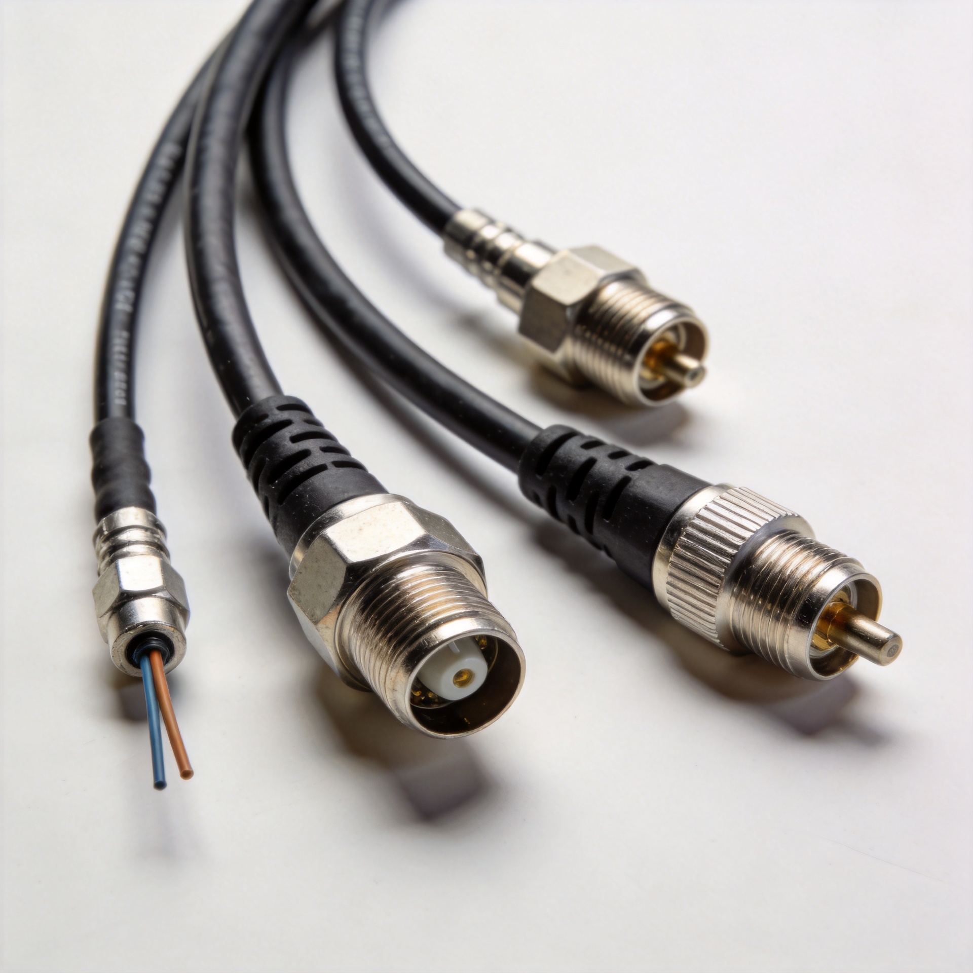
OEM work is valuable when it makes a repeatable assembly easier to build. A supplier focused on RF connectors and cable assemblies can review a requested connector format alongside cable length, mixed-connector configurations, and application-specific outer-conductor or jacket needs. For Worldpeak’s stated capabilities, custom cable assemblies may be made in non-standard lengths and connector combinations, which is relevant when a compact enclosure has a fixed routing path.
Electrical verification should also be planned early. For critical cable assemblies, Worldpeak’s CMS-confirmed variable library describes pre-shipment insertion-loss and VSWR sweep measurement with test data included in shipment documentation. Whether that testing is appropriate, and which limits apply, should be agreed for the specific build. It is a useful way to connect the mechanical drawing with an incoming-inspection process rather than treating RF performance as an afterthought.
A practical OEM SMA connector checklist
- Define the radio band, system impedance, and acceptance criteria for the complete RF path.
- Provide the enclosure drawing, panel thickness, keep-out zones, and desired external access direction.
- Specify the SMA connector mounting style, mating interface, thread details, and anti-rotation needs.
- Map cable length, exit direction, allowed bend area, and strain-relief clearance before tooling or pilot assembly.
- Request samples or a first-article build for fit, mating, torque access, and RF verification.
- Document the agreed inspection items, including any insertion-loss or VSWR requirements for cable assemblies.
Choose the connector around the product, not the other way around
A compact IoT device does not need a complicated connector program. It needs a connector decision that reflects real board space, enclosure geometry, antenna access, and production handling. An OEM-customized SMA connector is a practical option when the standard interface is right for the RF system but the physical implementation needs to be defined around a specific product.
By treating the connector, cable assembly, enclosure, and test plan as one design-in package, teams can reduce late-stage fit changes and create a clearer path from prototype to repeatable production. The result is not a universal SMA configuration; it is a documented interface that fits the communication hardware it is meant to serve.
SMA connector design review points
Use this SMA connector review at each design gate. Confirm the SMA connector footprint before the PCB is released. Confirm the SMA connector panel location before the enclosure drawing is frozen. Confirm the SMA connector mating side before antenna selection. Confirm the SMA connector cable exit before harness routing. Confirm the SMA connector thread reach before final assembly. Confirm the SMA connector torque access before service instructions are approved.
During pilot production, inspect the SMA connector location against the approved drawing. Check that the SMA connector does not interfere with batteries, shields, or fasteners. Verify that the SMA connector cable bend remains within the assembly allowance. Record the SMA connector mating requirement in the work instruction. Where the RF path is critical, include the SMA connector assembly in the agreed electrical verification plan.
This repeated review is practical because an SMA connector touches mechanical, RF, and manufacturing decisions at once. A well-defined SMA connector reduces ambiguity for the PCB team, enclosure supplier, cable assembler, and incoming-inspection team. The final SMA connector specification should therefore travel with the product drawing and validation records.