 EN
EN

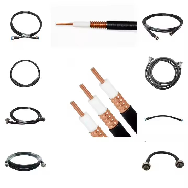
In commercial telecommunications, test and measurement benches, and mobile radio networks, an rg58 jumper serves as the vital link spanning the final distance between active hardware and fixed distribution infrastructure. Whether connecting a VHF/UHF transceiver to an antenna tuning unit, linking an oscilloscope to a signal tap, or bridging lightning surge protectors in a base station rack, coaxial patch leads must maintain continuous electromagnetic shielding and predictable signal attenuation. While short cable runs might seem forgiving, treating an rg58 jumper as an arbitrary accessory risks introducing unacceptable insertion loss, standing wave reflections, and mechanical fatigue into an otherwise optimized link budget.
System integrators and engineering procurement teams must evaluate characteristic impedance, dielectric stability, shield coverage, and connector termination methods. Selecting an assembly based solely on catalog photos or generic labeling creates preventable field failures.
Role of Coaxial Jumpers in High-Frequency Signal Paths
A flexible cable coaxial rg58 50 ohms assembly functions as a balanced distributed transmission line. The nominal 50-ohm characteristic impedance is governed by the precise physical ratio between the center conductor outer diameter and the shield inner diameter, in combination with the dielectric constant of the insulating core material. In standard communications systems, matching this nominal impedance prevents signal reflections back into high-power transmitters.
Every RF jumper contributes to total path attenuation and system noise figure. Even across short distances of three to ten feet, an rg58 jumper introduces insertion loss that escalates as frequency rises. For VHF tactical radios operating below 150 MHz, attenuation remains modest. However, when deployed in UHF telemetry, cellular bands, or industrial Wi-Fi setups, excessive line loss compromises receiver sensitivity. Treating the rg58 interconnect as an active element in the link budget ensures that RF margins remain robust under varying operational conditions.
Critical Construction Factors and Dielectric Profiles
Navigating published rg58 coaxial cable specifications requires distinguishing between nominal military-standard constructions (such as MIL-C-17 variants) and commercial utility grades. Significant variations in conductor metallurgy, dielectric composition, and shield coverage directly govern electrical and mechanical longevity.
Standard rg58 cable utilizes a 20 AWG solid or stranded tinned copper center conductor surrounded by solid polyethylene (PE) dielectric insulation. Higher-grade low-loss variations employ foamed polyethylene (FPE), which introduces microscopic gas pockets to lower the effective dielectric constant and boost the velocity of propagation from roughly 66% up to 80%. Shielding architecture represents another critical differentiator: basic commercial grades often provide single bare-copper braid coverage around 70% to 80%, whereas military-specification and industrial-grade cables feature 95% tinned copper braiding or dual-layer foil-plus-braid designs to prevent RF leakage and external EMI pickup.
Parameter
Solid Polyethylene (PE) RG58
Foam Polyethylene (FPE) Low-Loss RG58
Characteristic Impedance
50 Ω (±2 Ω)
50 Ω (±2 Ω)
Velocity of Propagation
66% Nominal
80% to 82% Nominal
Nominal Capacitance
101 pF/m (30.8 pF/ft)
82 pF/m (25.0 pF/ft)
Center Conductor Construction
20 AWG Solid (0.81 mm) or Stranded (19×0.18 mm)
19 AWG to 20 AWG Solid Bare Copper
Shield Braid Coverage
95% Tinned Copper Braid
Dual Layer: Aluminum Foil + 90% Tinned Braid
Nominal Cable Diameter
4.95 mm (0.195 inches)
4.95 mm (0.195 inches)
Standard Jacket Material
Non-Contaminating Polyvinyl Chloride (PVC)
Low Smoke Zero Halogen (LSZH) or UV-PVC
Operating Temperature Range
-40°C to +85°C
-40°C to +85°C
| Parameter | Solid Polyethylene (PE) RG58 | Foam Polyethylene (FPE) Low-Loss RG58 |
|---|---|---|
| Characteristic Impedance | 50 Ω (±2 Ω) | 50 Ω (±2 Ω) |
| Velocity of Propagation | 66% Nominal | 80% to 82% Nominal |
| Nominal Capacitance | 101 pF/m (30.8 pF/ft) | 82 pF/m (25.0 pF/ft) |
| Center Conductor Construction | 20 AWG Solid (0.81 mm) or Stranded (19×0.18 mm) | 19 AWG to 20 AWG Solid Bare Copper |
| Shield Braid Coverage | 95% Tinned Copper Braid | Dual Layer: Aluminum Foil + 90% Tinned Braid |
| Nominal Cable Diameter | 4.95 mm (0.195 inches) | 4.95 mm (0.195 inches) |
| Standard Jacket Material | Non-Contaminating Polyvinyl Chloride (PVC) | Low Smoke Zero Halogen (LSZH) or UV-PVC |
| Operating Temperature Range | -40°C to +85°C | -40°C to +85°C |
Reviewing verified rg58 coaxial cable specifications ensures that the chosen dielectric and jacket materials match the mechanical and thermal demands of the target operating environment.
Flexible Coaxial Cable Selection and Trade-Offs
Engineers frequently weigh an rg58 jumper against alternative 50-ohm coaxial assemblies such as RG8X, RG142, and LMR-class low-loss cables. Choosing the optimal transmission line involves balancing flexibility, physical diameter, attenuation per unit length, and budgetary constraints.
Cable Type
Nominal Outer Diameter
Attenuation at 400 MHz (per 100 ft)
Minimum Dynamic Bend Radius
Typical High-Priority Application
Standard RG58
4.95 mm (0.195 in)
~11.6 dB
50.0 mm (1.97 in)
Test bench patch leads, mobile radio jumpers
RG8X (Mini-8)
6.15 mm (0.242 in)
~7.5 dB
62.0 mm (2.44 in)
Marine VHF, intermediate HF/VHF feeder runs
RG142 High-Temp
4.95 mm (0.195 in)
~9.2 dB
50.0 mm (1.97 in)
Aerospace, military radar, high-temperature avionics
LMR-195 Class
4.95 mm (0.195 in)
~6.2 dB
50.0 mm (1.97 in)
High-frequency wireless infrastructure, drop-in upgrade
LMR-400 Class
10.29 mm (0.405 in)
~2.7 dB
101.6 mm (4.00 in)
Primary base station trunk lines, long antenna feeds
| Cable Type | Nominal Outer Diameter | Attenuation at 400 MHz (per 100 ft) | Minimum Dynamic Bend Radius | Typical High-Priority Application |
|---|---|---|---|---|
| Standard RG58 | 4.95 mm (0.195 in) | ~11.6 dB | 50.0 mm (1.97 in) | Test bench patch leads, mobile radio jumpers |
| RG8X (Mini-8) | 6.15 mm (0.242 in) | ~7.5 dB | 62.0 mm (2.44 in) | Marine VHF, intermediate HF/VHF feeder runs |
| RG142 High-Temp | 4.95 mm (0.195 in) | ~9.2 dB | 50.0 mm (1.97 in) | Aerospace, military radar, high-temperature avionics |
| LMR-195 Class | 4.95 mm (0.195 in) | ~6.2 dB | 50.0 mm (1.97 in) | High-frequency wireless infrastructure, drop-in upgrade |
| LMR-400 Class | 10.29 mm (0.405 in) | ~2.7 dB | 101.6 mm (4.00 in) | Primary base station trunk lines, long antenna feeds |
When tight packaging, high flexibility, and frequent manual handling define the assembly, a flexible cable coaxial rg58 50 ohms lead provides an optimal mechanical solution. If the installation demands long feeder runs exceeding 20 feet or higher operating frequencies above 1 GHz, migrating to larger low-loss cable architectures preserves critical link power.
Precision Connector Termination and Interface Matching
A complete rg58 jumper is only as reliable as its end terminations. Interfacing with laboratory equipment, transceivers, and antennas requires selecting matched 50-ohm connector families, including BNC, TNC, SMA, and N-type terminations.
-
BNC Connectors: Deliver quick-disconnect bayonet locking ideal for indoor laboratory oscilloscopes, video monitoring, and test benches.
-
TNC Connectors: Provide threaded vibration resistance for mobile vehicular radios, avionics, and industrial automation equipment.
-
SMA Connectors: Offer compact, lightweight 50-ohm threaded interfaces for microwave modules, telemetry cards, and embedded communications.
-
N-Type Connectors: Supply medium-sized, weather-sealed threaded couplings suitable for outdoor antenna feeders, surge arrestors, and base station cabinets.
Controlled hex crimping represents the manufacturing standard for terminating cable coaxial rg58 50 ohms stock. Calibrated ratcheting crimp dies compress the metal ferrule symmetrically over the cable braid and body without deforming the internal dielectric core. For applications subjected to severe cyclic vibration, combining a crimped outer ferrule with a gold-plated center pin soldered directly to the stranded core prevents contact fretting and intermittent open circuits.
Mechanical Routing Rules and Bend Radius Limitations
Mechanical routing mistakes degrade RF performance long before the physical cable jacket tears. Coaxial transmission lines depend on concentric conductor geometry. Forcing a tight bend crushes the soft PE or FPE dielectric, pushing the center conductor closer to the outer shield braid. This physical distortion creates an immediate localized impedance dip, resulting in high VSWR spikes and elevated signal reflection.
-
Maintain a continuous static bend radius of at least five times the cable outer diameter (approximately 25 mm or 1.0 inch) for fixed chassis routes.
-
Enforce a dynamic bend radius of at least ten times the outer diameter (roughly 50 mm or 2.0 inches) for test leads subject to repeated movement.
-
Position molded heat-shrink tubing or elastomeric strain-relief boots over connector rear sleeves to prevent sharp mechanical kinks at the ferrule edge.
-
Secure long cable runs with padded support clamps or hook-and-loop fasteners rather than overtightened zip ties that crush and distort internal rg58 coaxial cable specifications.
Following these mechanical guidelines ensures the finished rg58 jumper sustains low reflection coefficients throughout extended service lifespans.
Quality Verification and Environmental Protection Standards
Deploying coaxial jumpers outdoors or in high-humidity industrial cabinets demands comprehensive weatherproofing and quality validation protocols:
-
Apply dual-layer weatherproofing using self-amalgamating silicone mastic tape covered by heavy-duty UV-resistant vinyl tape to seal outdoor mated joints.
-
Conduct high-voltage direct current (hipot) insulation testing at 1000V DC to ensure no stray shield braid wires touch the internal center pin.
-
Perform 100% Vector Network Analyzer sweep testing across the target frequency band to verify insertion loss and return loss compliance.
-
Verify mechanical pull strength using calibrated tensile testing to confirm the crimped ferrule withstands axial pull forces exceeding 150 Newtons without braid slippage.
Confirming these verification steps ensures that each delivered rg58 jumper performs predictably in mission-critical wireless systems.
Precision Manufacturing and OEM Capabilities with Worldpeak
High-reliability RF applications require dependable manufacturing precision, structural consistency, and fully traceable testing documentation across every production batch. As a specialized RF hardware manufacturer and international exporter, Worldpeak delivers comprehensive design, precision machining, and OEM/ODM fabrication services for high-performance coaxial connectivity. Multi-axis CNC Swiss turning centers maintain machining tolerances down to ±0.005 mm on all connector interfaces, ensuring that every cable coaxial rg58 50 ohms termination provides exact concentricity and low contact resistance.
The automated cable assembly facilities at Worldpeak provide tailored length configurations, customized labeling, specialized right-angle connector integrations, and optimized strain-relief molding. Every production lot undergoes rigorous quality assurance, including 100% Vector Network Analyzer sweep testing for return loss and VSWR, XRF plating thickness verification, and environmental salt-spray testing. Whether supplying standard 50-ohm patch cables or engineered multi-conductor harnesses compliant with published rg58 coaxial cable specifications, Worldpeak supports global industrial and telecommunications clients with rapid prototyping, flexible minimum order quantities, and reliable international supply chain delivery.





