 EN
EN

What environmental resistance can be customized for OEM rf cable
2026/09/25
Customize an rf high frequency cable for temperature, moisture, corrosion, vibration, flexing, and OEM validation needs.
2026/09/11
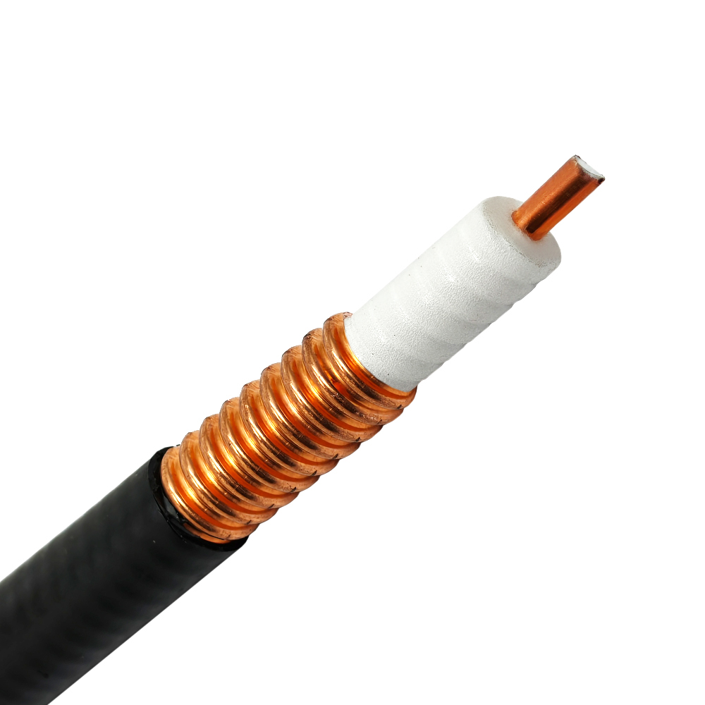
In enclosed infrastructure such as underground mining shafts, railway tunnels, metro transit corridors, and reinforced concrete basements, conventional point-source antennas suffer from severe line-of-sight signal blocking, multi-path fading, and rapid attenuation. Deploying a high-performance leaky feeder cable solves this fundamental coverage gap by functioning as a continuous linear antenna along the entire length of a route.
When designing high-reliability underground communications, selecting the correct RF leaky coaxial cable is essential to achieving stable signal propagation, low coupling loss, and low longitudinal attenuation. WORLDPEAK manufactures high-grade coaxial components and cable interconnect systems engineered for demanding industrial environments. This guide breaks down the operational physics, mechanical design, key deployment scenarios, and procurement criteria for choosing the right underground communication cable for long-distance signal continuity.
A standard coaxial cable is designed with a continuous, fully shielded outer conductor to retain 100% of the electromagnetic wave inside the cable dielectric. In contrast, an RF leaky coaxial cable is manufactured with precision-engineered slots, apertures, or perforations patterned along its outer copper or aluminum shield.
Signal Guided Propagation: As radio frequency signals travel down the inner conductor, a controlled fraction of electromagnetic energy escapes through the outer conductor slots into the surrounding space.
Bi-Directional Radiating & Receiving: The slots act as an infinite series of small magnetic dipoles. This design allows the cable to both broadcast signals to mobile handsets/radios and capture incoming signals from handheld transceivers.
Continuous Signal Distribution: Instead of relying on a single high-power antenna, the leaky feeder cable provides uniform RF field strength over several kilometers, making it an ideal passive solution for a distributed antenna system (DAS) in narrow corridors.
When specifying an underground communication cable for complex industrial projects, engineers must choose between two primary slot design configurations:
| Technical Parameter | Radiating Mode Leaky Feeder | Coupled Mode Leaky Feeder |
| Slot Configuration | Inclined, periodically spaced pitched slots | Random, continuous, or small uniform slots |
| Frequency Range | Narrowband / Tuned bands (e.g., 150 MHz, 450 MHz, 900 MHz, 1.8 GHz, 2.4 GHz) | Broadband capability (DC to 6 GHz) |
| Coupling Loss Performance | Low coupling loss, stable long-distance radiation | Higher coupling loss, localized radiation |
| Primary Deployment | High-speed rail tunnels, metro lines, long-distance highway tunnels | Building basements, utility ducts, short mining shafts |
| Signal Uniformity | Exceptional signal consistency over several kilometers | Subject to multi-path fading over long distances |
For long-range tunnel wireless coverage, radiating-mode cables are preferred because their slotted geometry minimizes longitudinal attenuation while optimizing radio coupling for specific frequency bands (VHF, UHF, TETRA, 4G LTE, and 5G NR).
Integrating an RF leaky coaxial cable eliminates dead zones across challenging subterranean and indoor environments where traditional wireless networks fail.
Underground mining relies on continuous voice, telemetry, and autonomous vehicle control signals. Deploying a heavy-duty leaky feeder cable along haulage drifts ensures seamless communication across VHF/UHF two-way radios, Wi-Fi data links, and LTE networks without requiring line-of-sight antenna alignment.
In high-speed transportation networks, trains pass through narrow concrete tunnels where external cell tower signals cannot penetrate. Installing an underground communication cable along the tunnel walls guarantees zero-handover drop rates for passenger cellular connectivity, emergency TETRA systems, and Train-to-Wayside Communication (CBTC).
For large commercial complexes, nuclear power plants, and underground parking facilities, an RF leaky coaxial cable serves as the backbone for an in-building distributed antenna system. It distributes multi-operator cellular coverage (3G/4G/5G) evenly across multi-level basements without creating high-power localized RF hotspots.
To maintain long-term signal integrity in high-moisture, corrosive, or high-vibration environments, procurement teams must evaluate strict material and testing benchmarks:
Jacket Material & Flame Retardancy: Outdoor and tunnel installations require Low-Smoke Zero-Halogen (LSZH) outer jackets compliant with IEC 60332-1, IEC 60332-3C, and CPR EN 50575 fire safety ratings.
Moisture Protection & IP Ratings: Corrosive mine water and high humidity can penetrate outer slots. High-quality cables utilize water-blocking tapes and corrosion-resistant foam PE dielectrics to achieve long-term environmental sealing.
PIM (Passive Intermodulation) Control: Multi-carrier LTE/5G systems require low PIM performance (<= -155 dBc @ 2 x 20W) to avoid inter-channel interference. WORLDPEAK provides precision RF connectors and low-PIM jumper assemblies engineered specifically for leaky feeder termination.
Coupling Loss vs. Longitudinal Attenuation Balancing: Lower attenuation allows longer cable runs without inline signal boosters (line amplifiers), while controlled coupling loss guarantees adequate signal power reaches mobile devices.
For complete product specifications, technical drawings, or volume B2B quotes, visit the technical hub at

2026/09/25
Customize an rf high frequency cable for temperature, moisture, corrosion, vibration, flexing, and OEM validation needs.

2026/09/25
Streamline RF equipment assembly lines with custom coaxial jumpers. Reduce line-side rework, ensure precise routing, and boost production efficiency.

2026/09/25
Learn PL-259 connector selection, soldering, weatherproofing, and RF applications for dependable antenna feedlines.

2026/09/25
Confirm impedance for a 90 degree coax connector with an ODM test plan covering VNA setup, VSWR, acceptance criteria, and release records.

2026/09/25
Learn when an n type coax connector can omit extra anti-corrosion treatment and when OEM exposure conditions require it.

2026/09/25
Learn how the custom cable and wire sample process helps ODM buyers validate design, testing, and production readiness.