 EN
EN

7/16 DIN Connector Guide: High-Power RF Standard
2026/09/24
Choose a 7 16 connector for high-power RF: compare DIN and Type N, protect PIM margin, and apply field installation checks.
2026/06/23
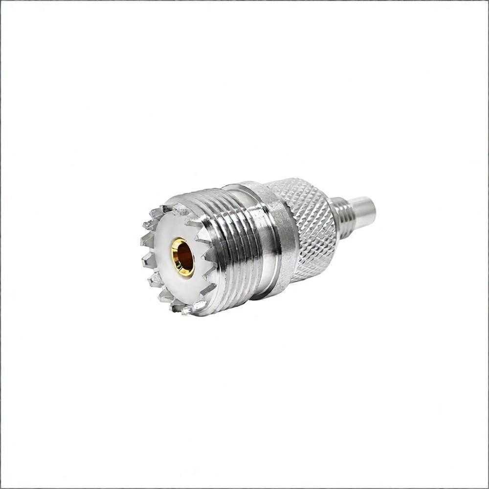
The Motorola R7 digital two-way radio features a proprietary antenna interface structure and does not offer native compatibility with industry-standard BNC connectors, making a professional dedicated adapter an essential accessory for external antenna connection and RF testing. This incompatibility originates from the R7 radio’s exclusive custom antenna interface design, which integrates a built-in RF test port at the base of the antenna socket for equipment diagnosis and signal detection. Direct installation and connection of conventional standard BNC connectors without an adapter will lead to physical structural interference, poor contact, and abnormal RF signal transmission. In severe cases, it may cause circuit short circuits and permanent damage to the radio’s internal RF modules. The detailed technical differences, adapter functions, product classifications and standardized usage specifications are systematically analyzed as follows.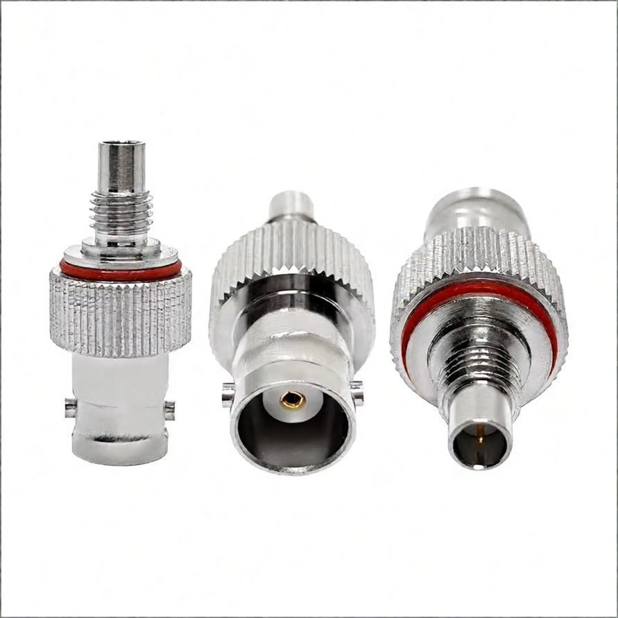
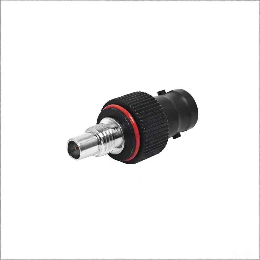
I. Interface Differences and Necessity of Adapters
1. R7’s Unique Interface Design
Different from traditional universal radio antenna interfaces, the Motorola R7’s antenna port integrates an independent RF diagnostic test port at the bottom of the socket, which is reserved for professional engineers to conduct RF signal detection, equipment fault diagnosis and performance calibration. Standard universal BNC connectors do not match this dual-port structural design at all. Improper and forced installation will cause the metal contacts of the BNC connector to mistakenly touch and short-circuit the reserved test port. This wrong contact state not only distorts normal RF signal transmission but also brings risks of static breakdown and current leakage, resulting in unstable radio operation or even irreversible hardware damage. The original supporting antenna of the R7 radio adopts a special notched base structural design, which can perfectly avoid the test port and achieve accurate docking, while ordinary standard BNC connectors have no targeted structural adaptation function.
2. Limitations of Standard BNC Connectors
In addition to structural mismatches, standard BNC connectors also have inherent impedance parameter defects that cannot adapt to the R7 radio’s working characteristics. Most conventional standard BNC connectors are designed with 75Ω characteristic impedance, which is widely applied in traditional video transmission systems and low-frequency signal equipment. In contrast, the Motorola R7 radio works in the 400–527 MHz professional communication frequency band and strictly requires a 50Ω standard RF transmission system to support efficient radio signal transceiving. Direct use of 75Ω BNC connectors will cause serious impedance mismatch, triggering severe signal reflection. Relevant test data shows that the reflection loss caused by this mismatch can exceed 30%, greatly reducing communication sensitivity, weakening signal penetration, and seriously affecting the radio’s normal communication performance.
II. Core Functions of Dedicated Adapters
1. Physical Compatibility
Professional dedicated R7 adapters are specially optimized for the radio’s unique interface structure, with the core design goal of achieving safe and stable physical docking. The adapter extends the core signal contact structure through precision structural design, effectively bypassing the built-in test port of the R7 interface and ensuring that only the primary signal pin is accurately connected to complete normal signal transmission. Its key optimized structures include an extended insulating body, which completely isolates the test port to avoid short-circuit interference, and customized precision threads, which perfectly fit the R7 radio’s non-standard thread pitch to prevent loosening and poor contact caused by mismatched threads.
2. Impedance Matching
High-quality dedicated R7 adapters strictly follow the 50Ω professional RF standard, adopting high-precision gold-plated conductive contacts. This design can effectively suppress signal reflection and attenuation, achieving excellent impedance matching effect. The Voltage Standing Wave Ratio (VSWR) of qualified dedicated adapters is controlled within ≤1.2 in the working frequency band, ensuring high-fidelity signal transmission. In comparison, generic universal adapters often have rough production processes and unstable impedance parameters, with a VSWR of ≥1.5, which cannot meet the R7 radio’s high-precision communication requirements and will cause continuous signal loss during long-term use.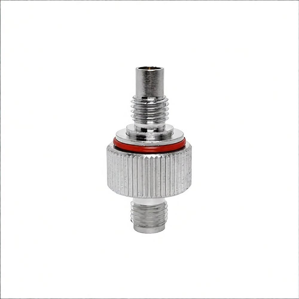
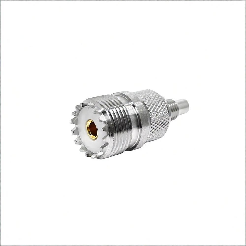
III. Common Adapter Types
1. Unidirectional Adapter (R7 Female → BNC Male)
This is the most widely used universal adapter model, mainly applied to connect the Motorola R7 radio with various standard BNC external antennas and professional RF test equipment such as spectrum analyzers and signal testers. Its standard technical specifications fully cover the daily use needs of the radio: the effective frequency range is DC–3 GHz, which completely includes the R7’s 400–527 MHz working frequency band with sufficient performance margin. The main body is made of nickel-plated and gold-plated brass composite materials, which has excellent corrosion resistance, oxidation resistance and ultra-low contact resistance, ensuring stable transmission performance in long-term outdoor and industrial environments. The bulk purchase price of this adapter is stable at $1.5–2.5 per unit, with high cost performance for batch deployment.
2. Dual-Port Test Adapter
The dual-port test adapter is a professional engineering accessory optimized for debugging and monitoring scenarios. Its core advantage is that it can retain the access function of the original test port while connecting the external antenna, realizing real-time RF signal monitoring, equipment performance testing and fault diagnosis without disassembling the antenna. It is mainly used in professional engineering debugging, communication equipment maintenance and laboratory signal monitoring scenarios. It is worth noting that this test port has strict power-bearing limitations. It cannot bear high-power transmission signals for a long time, otherwise it will cause internal circuit overload and permanent component damage, so it is only suitable for low-power signal detection rather than formal communication transmission work.
IV. Usage Precautions
1. Avoid Direct Antenna Modification
Forcing unqualified non-standard adapters or privately modifying antenna interfaces to adapt to BNC connectors will bring multiple potential risks. First, there is an ESD static electricity hazard: external antennas installed outdoors are prone to static accumulation, and the ungrounded modified structure will conduct static electricity through the R7 test port, directly impacting and damaging internal precision RF components. Second, severe impedance mismatch will cause excessive VSWR fluctuation. When the radio transmits at a rated power of 5W, continuous mismatched signals will cause heat accumulation in the power amplifier module, leading to performance attenuation or even burnout of key components.
2. Selection Guidelines
In actual selection and matching work, three core criteria must be followed. First, confirm the 50Ω professional communication rating, and resolutely eliminate 75Ω video-grade BNC adapters with mismatched parameters. Second, verify the test port isolation performance, and prioritize premium adapters marked with "Test Port Safe" or equipped with clear isolation protection mechanisms to avoid short-circuit risks. Third, select products with all-metal housings; plastic housing adapters are prone to loosening due to vibration and temperature changes during use, resulting in intermittent signal loss and unstable communication. For long-term external antenna deployment, Motorola certified dedicated adapters or official OEM customized solutions are strongly recommended. Unauthorized modification and use of non-standard accessories will not only void the official warranty but also bring potential safety hazards. For high-standard professional RF deployment scenarios, a vector network analyzer should be used to calibrate VSWR and verify impedance matching before formal use to ensure stable and reliable equipment operation.

2026/09/24
Choose a 7 16 connector for high-power RF: compare DIN and Type N, protect PIM margin, and apply field installation checks.

2026/09/24
Compare TNC connector types, specs and applications, including RP-TNC, bulkhead options, vibration performance and adapter selection.

2026/09/24
Understand MMCX connector basics, RF limits, and how to choose the right coaxial interface for compact systems.

2026/09/24
Understand RP-SMA connector polarity, mating rules, frequency checks, and OEM termination options for reliable RF builds.

2026/09/24
Choose the right bnc male connector for RF, CCTV and test systems with clear 50Ω vs 75Ω, type and installation guidance.

2026/09/24
Compare LMR400 specs, cable loss, uses, connectors and RG8/RG213 alternatives with a practical RF loss-budget method.