 EN
EN

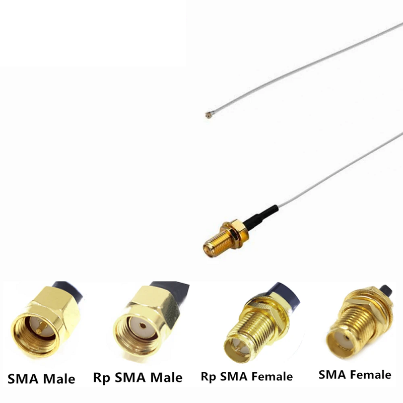
In cellular gateways, Wi-Fi base stations, GPS positioning modules, and laboratory test fixtures, a standard connector sma male often appears as a routine bill-of-materials line item. However, integration errors frequently surface during final board assembly or box-level interconnect fitting. A mismatched thread orientation, improper center pin diameter, or an unoptimized printed circuit board footprint can ruin impedance matching, introduce unacceptable return loss, or physically crush delicate internal contacts.
Successful radio frequency deployment demands evaluating the mechanical mating interface, substrate stack-up, and manufacturing assembly protocols in parallel. Treating every subminiature version A component as interchangeable is one of the most common oversights in modern RF hardware engineering.
Interface Anatomy and Pin Dimension Specifications
A standard SMA interface operates across a characteristic 50-ohm impedance environment with a coupling thread defined by the 1/4-36 UNS specification. Mechanical precision at the interface determines whether the high-frequency electromagnetic wave transitions smoothly or generates destructive reflections.
On a standard connector sma male, the rotating outer coupling nut features internal threads, while the gold-plated center conductor is an exposed, solid cylindrical pin. The standard mating counterpart is a female jack, featuring external body threads and a precision female socket.
Mechanical Feature
Nominal Dimension (Metric)
Nominal Dimension (Imperial)
Critical Engineering Tolerance
Center Male Pin Diameter
0.90 mm to 0.94 mm
0.0355 in to 0.0370 in
Critical for mating contact force and VSWR
Male Pin Protrusion Length
2.54 mm minimum
0.100 in minimum
Prevents pin bottoming or insufficient engagement
Outer Coupling Thread
1/4-36 UNS-2B (Internal)
1/4-36 UNS-2B (Internal)
Requires calibrated hex wrench clearance
Dielectric Core (PTFE) Diameter
4.13 mm
0.1625 in
Controls 50-ohm air-to-dielectric boundary
Hex Nut Outer Width
8.00 mm
5/16 in hex
Prevents shell deformation under rated torque
| Mechanical Feature | Nominal Dimension (Metric) | Nominal Dimension (Imperial) | Critical Engineering Tolerance |
|---|---|---|---|
| Center Male Pin Diameter | 0.90 mm to 0.94 mm | 0.0355 in to 0.0370 in | Critical for mating contact force and VSWR |
| Male Pin Protrusion Length | 2.54 mm minimum | 0.100 in minimum | Prevents pin bottoming or insufficient engagement |
| Outer Coupling Thread | 1/4-36 UNS-2B (Internal) | 1/4-36 UNS-2B (Internal) | Requires calibrated hex wrench clearance |
| Dielectric Core (PTFE) Diameter | 4.13 mm | 0.1625 in | Controls 50-ohm air-to-dielectric boundary |
| Hex Nut Outer Width | 8.00 mm | 5/16 in hex | Prevents shell deformation under rated torque |
When designing or inspecting an sma male to female interface or an inline adapter, verify the internal socket fingers on the female receptacle. If an oversized center contact has historically penetrated the jack, the socket tines can splay outward, leading to intermittent signal dropouts and degraded passive intermodulation performance.
Polarity Rules and Reverse Polarity Mismatches
Regulatory frameworks in commercial wireless communications popularized reverse-polarity designs to prevent unauthorized antenna upgrades. While standard and reverse-polarity parts share identical thread pitches, their center contacts are inverted.
Mixing standard components with reverse-polarity counterparts produces severe physical damage or electrical opens:
-
Standard SMA Male: Internal coupling thread, protruding solid center pin.
-
Standard SMA Female: External body thread, internal recessed center receptacle.
-
RP-SMA Male: Internal coupling thread, internal recessed center receptacle.
-
RP-SMA Female: External body thread, protruding solid center pin.
Connector Interface Type
Coupling Thread Location
Center Contact Geometry
Normal Mating Counterpart
Standard Male
Internal (1/4-36 UNS)
Protruding Male Pin
Standard Female Receptacle
Standard Female
External (1/4-36 UNS)
Recessed Female Socket
Standard Male Pin
Reverse-Polarity Male
Internal (1/4-36 UNS)
Recessed Female Socket
Reverse-Polarity Female Pin
Reverse-Polarity Female
External (1/4-36 UNS)
Protruding Male Pin
Reverse-Polarity Male Socket
| Connector Interface Type | Coupling Thread Location | Center Contact Geometry | Normal Mating Counterpart |
|---|---|---|---|
| Standard Male | Internal (1/4-36 UNS) | Protruding Male Pin | Standard Female Receptacle |
| Standard Female | External (1/4-36 UNS) | Recessed Female Socket | Standard Male Pin |
| Reverse-Polarity Male | Internal (1/4-36 UNS) | Recessed Female Socket | Reverse-Polarity Female Pin |
| Reverse-Polarity Female | External (1/4-36 UNS) | Protruding Male Pin | Reverse-Polarity Male Socket |
A dangerous mismatch occurs when attempting to join a standard connector sma male with an RP-SMA female jack. Because the outer shells thread together seamlessly, an installer may apply full coupling torque without realizing that two solid brass center pins are colliding head-on inside the dielectric chamber. This catastrophic interference buckles both pins, splits the internal PTFE insulator, and destroys the board-mounted jack.
For industrial telemetry and commercial base stations, confirm a dedicated sma male to sma female connection throughout the signal chain. Conversely, for dual-band consumer Wi-Fi equipment and unlicensed wireless equipment, ensure the entire assembly path maintains an rp sma male to rp sma female configuration. Never substitute adapters based on exterior shell appearance alone.
PCB Mount Architecture and RF Launch Considerations
Transitioning high-frequency microwave energy from a coaxial geometry to a planar printed circuit board requires choosing an appropriate board-mount package. The physical transition creates an electrical discontinuity that must be compensated for via proper land pattern geometry, ground plane stitching, and substrate selection.
Mounting Configuration
Typical Frequency Limit
PCB Thickness Compatibility
Assembly Method
Best-Fit Application Environment
Edge-Launch (End-Launch)
Up to 18.0 GHz (or 26.5 GHz)
0.8 mm to 2.4 mm (Adjustable)
SMT / Hand Solder Clamp
Controlled-impedance coplanar microstrip
Vertical Through-Hole
Up to 6.0 GHz
1.6 mm standard boards
Wave Solder / Selective Solder
High-vibration chassis with top enclosure access
Right-Angle Through-Hole
Up to 4.0 GHz
1.2 mm to 1.6 mm
Through-hole wave soldering
Low-profile enclosures with tight z-axis height
Surface Mount (SMT) Jack
Up to 8.0 GHz
Independent of thickness
Standard SMT Convection Reflow
Automated pick-and-place high-volume consumer boards
| Mounting Configuration | Typical Frequency Limit | PCB Thickness Compatibility | Assembly Method | Best-Fit Application Environment |
|---|---|---|---|---|
| Edge-Launch (End-Launch) | Up to 18.0 GHz (or 26.5 GHz) | 0.8 mm to 2.4 mm (Adjustable) | SMT / Hand Solder Clamp | Controlled-impedance coplanar microstrip |
| Vertical Through-Hole | Up to 6.0 GHz | 1.6 mm standard boards | Wave Solder / Selective Solder | High-vibration chassis with top enclosure access |
| Right-Angle Through-Hole | Up to 4.0 GHz | 1.2 mm to 1.6 mm | Through-hole wave soldering | Low-profile enclosures with tight z-axis height |
| Surface Mount (SMT) Jack | Up to 8.0 GHz | Independent of thickness | Standard SMT Convection Reflow | Automated pick-and-place high-volume consumer boards |
Edge-launch designs provide the cleanest coaxial-to-planar transition. Positioning the center pin along the horizontal board edge minimizes parasitic shunt capacitance. However, the engineer must tune the top-layer coplanar ground spacing and create an antipad relief directly beneath the signal pad on intermediate layers. Without proper antipad cutouts, the transition zone creates a capacitive dip in time-domain reflectometry measurements.
Through-hole configurations offer exceptional mechanical shear resistance against external cable pulling forces. Nevertheless, through-hole connector legs act as open-ended inductive and capacitive stubs at frequencies above 6 GHz. If wideband microwave operation is required, edge-launch or dedicated surface-mount transitions are preferred.
Cable Termination and Assembly Protocols
Securing a connector sma male to a flexible, conformable, or semi-rigid coaxial transmission line demands calibrated production methods. An inconsistent crimp or poor solder penetration degrades return loss and limits mechanical durability.
Termination Method
Target Coaxial Cable Family
Tooling and Process Controls
Mechanical Pull Strength
Primary Quality Inspection Metrics
Hex Crimp with Solder Pin
RG-58, LMR-195, LMR-240
Calibrated ratcheting crimper
> 150 N (33.7 lbf)
Crimp sleeve hex height, pin solder fillet
Full Crimp (Pin and Ferrule)
RG-174, RG-316, RG-178
Automated benchtop crimp press
> 80 N (18.0 lbf)
Pin push-back force, insulation gap
Direct Solder Clamp
Semi-Rigid (.086, .141 inch)
Temperature-controlled induction
Cable tensile limit
360-degree solder fillet without thermal overflow
| Termination Method | Target Coaxial Cable Family | Tooling and Process Controls | Mechanical Pull Strength | Primary Quality Inspection Metrics |
|---|---|---|---|---|
| Hex Crimp with Solder Pin | RG-58, LMR-195, LMR-240 | Calibrated ratcheting crimper | > 150 N (33.7 lbf) | Crimp sleeve hex height, pin solder fillet |
| Full Crimp (Pin and Ferrule) | RG-174, RG-316, RG-178 | Automated benchtop crimp press | > 80 N (18.0 lbf) | Pin push-back force, insulation gap |
| Direct Solder Clamp | Semi-Rigid (.086, .141 inch) | Temperature-controlled induction | Cable tensile limit | 360-degree solder fillet without thermal overflow |
When installing a straight or right-angle connector sma male onto braided cables, cable stripping dimensions must strictly match manufacturer drawing callouts. Excessive braid trimming leaves an unshielded segment that radiates RF energy, whereas insufficient braid capture causes the crimp ferrule to loosen over operational thermal cycles.
For field installations connecting an sma male to female jumper, strain relief boots and adhesive-lined heat shrink tubing prevent acute bending moments at the rear connector collar.
Torque Limits, Environmental Sealing, and Reliability
Proper mechanical installation prevents interface damage while ensuring electrical continuity across fluctuating operating temperatures. Over-tightening an SMA interface distorts the PTFE dielectric and gouges the gold plating on mating surfaces, while under-tightening generates passive intermodulation instability and high contact resistance.
-
Brass Connector Body Torque: 0.35 to 0.57 N·m (3 to 5 in-lbs).
-
Stainless Steel Body Torque: 0.80 to 1.10 N·m (7 to 10 in-lbs).
-
Recommended Tool: Calibrated 8 mm (5/16 in) break-over torque wrench.
In harsh outdoor deployments, an unsealed sma male to sma female connection allows moisture ingress through capillary action along the coupling threads. Specifying connectors with internal silicone O-rings, alongside secondary IP67 or IP68 mastic tape weatherproofing, preserves signal integrity across years of environmental exposure.
Comprehensive RF Connector Selection Checklist
Before releasing production drawings or issuing procurement purchase orders, verify the transmission line against this engineering checklist:
Verification Stage
Engineering Checkpoint
Actionable Decision Rule
Polarity Verification
Pin and thread configuration
Check for standard pin-in-male or reverse-polarity pin-in-female.
Mating Matching
End-to-end interface compatibility
Never mate standard SMA parts with reverse-polarity interfaces.
Frequency & VSWR
System bandwidth target
Confirm connector rating exceeds upper cutoff frequency by 15%.
PCB Stack-up Alignment
Board dielectric and thickness
Match edge-launch gap to copper-clad laminate thickness.
Cable Interface
Cable construction and outer jacket
Match ferrule cavity dimensions to exact braid diameters.
Assembly Inspection
Quality control sampling
Verify first-article pin protrusion dimensions with optical comparators.
| Verification Stage | Engineering Checkpoint | Actionable Decision Rule |
|---|---|---|
| Polarity Verification | Pin and thread configuration | Check for standard pin-in-male or reverse-polarity pin-in-female. |
| Mating Matching | End-to-end interface compatibility | Never mate standard SMA parts with reverse-polarity interfaces. |
| Frequency & VSWR | System bandwidth target | Confirm connector rating exceeds upper cutoff frequency by 15%. |
| PCB Stack-up Alignment | Board dielectric and thickness | Match edge-launch gap to copper-clad laminate thickness. |
| Cable Interface | Cable construction and outer jacket | Match ferrule cavity dimensions to exact braid diameters. |
| Assembly Inspection | Quality control sampling | Verify first-article pin protrusion dimensions with optical comparators. |
Precision Manufacturing and Supply Chain Partnership
Sourcing reliable RF interconnects demands a production partner capable of delivering micron-level machining precision, stable raw materials, and documented quality inspection. WORLDPEAK manufactures an extensive portfolio of precision standard SMA, reverse-polarity, and custom board-level connectors engineered for demanding aerospace, telecommunications, and industrial automation applications.
From low-loss connector sma male cable assemblies to customized edge-launch PCB jacks designed for high-frequency low-VSWR applications, WORLDPEAK maintains strict CNC machining tolerances and automated plating controls. With complete OEM and ODM engineering support, comprehensive ISO quality certifications, and flexible global delivery capabilities, WORLDPEAK provides the RF hardware reliability that keeps high-performance communications equipment operating without compromise.





