 EN
EN

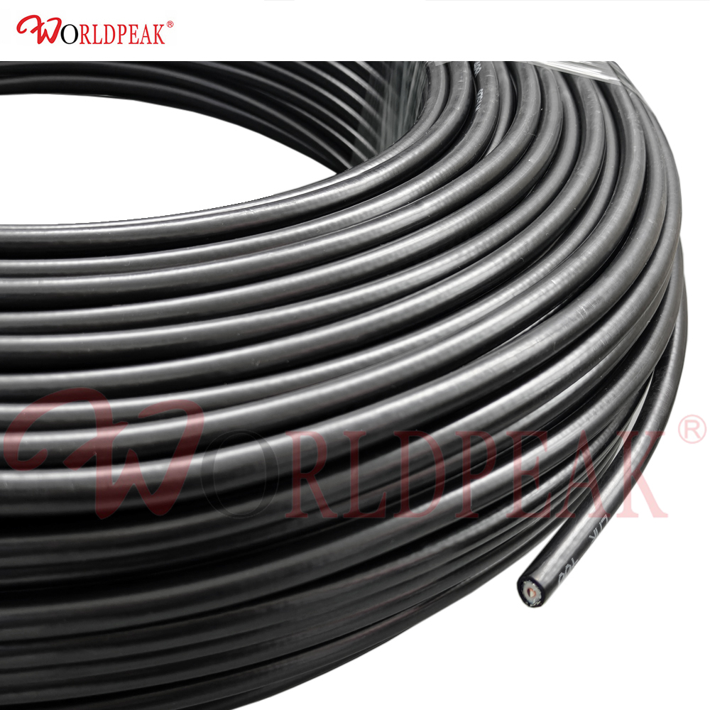
In wireless telecommunications, cellular distributed antenna networks, satellite ground stations, and high-frequency microwave backhauls, feeder line selection directly dictates overall link performance. As operational frequencies expand into upper UHF and SHF spectrums, signal attenuation across lengthy cable runs becomes a dominant factor in system link budgets. The lmr 400 coax has emerged as the global industry benchmark for low-loss 50-ohm transmission lines, replacing legacy corrugated copper and bulky solid dielectric cables. Deploying this high-performance line requires a comprehensive understanding of conductor metallurgy, dielectric dynamics, dynamic bend limits, and connector termination methods.
Treating an lmr 400 50 ohm coax cable as an isolated hardware commodity frequently introduces unexpected insertion loss, elevated Voltage Standing Wave Ratio (VSWR), and premature weather ingress. Precision RF deployment requires balancing electromagnetic efficiency with mechanical packaging constraints.
Physical Architecture and Dielectric Properties of LMR-400
The superior attenuation characteristics of lmr 400 coax stem from its engineered composite structural architecture. Traditional flexible coaxial lines rely on solid polyethylene dielectrics and single-layer woven wire braids, which exhibit substantial capacitive losses and radio frequency leakage at frequencies above 1 GHz.
Standard lmr 400 cable incorporates a 2.74 mm (0.108 inches) solid bare copper-clad aluminum (BCCAI) center conductor. At radio frequencies, electrical current travels almost exclusively within the outer microscopic skin layer of pure copper due to the skin effect. The lightweight aluminum inner core reduces total cable weight while maintaining high tensile strength and electrical conductivity.
Surrounding the center conductor is a closed-cell, gas-injected foamed polyethylene (FPE) dielectric core. By introducing microscopic inert nitrogen gas bubbles into the dielectric material, the effective dielectric constant is significantly lowered. This reduction delivers an exceptional velocity of propagation of 85%, cutting dielectric dissipation factors compared to solid insulators.
-
Primary Inner Shield: 100% coverage aluminum tape bonded directly to the foamed dielectric core eliminates high-frequency RF leakage.
-
Secondary Outer Shield: 34 AWG tinned copper wire braid providing 85% to 90% optical coverage ensures continuous mechanical grounding.
-
Outer Weatherproof Protective Jacket: Non-contaminating, UV-resistant black polyethylene (PE) engineered to withstand decades of direct sunlight, ozone, and ground burial.
This dual-layer shielding topology delivers continuous shielding effectiveness exceeding 90 dB, preventing cross-talk in dense equipment trays and isolating sensitive receiver paths from high-power ambient interference.
Standard LMR-400 versus LMR-400 UltraFlex Construction
System integrators frequently encounter tight internal equipment enclosures, dynamic antenna rotators, and articulating mast assemblies where the mechanical stiffness of standard lmr 400 cable presents installation challenges. In these configurations, evaluating an lmr 400 ultraflex variant becomes essential.
The mechanical distinction centers on internal conductor composition and outer jacket polymers:
Standard lmr 400 coax utilizes a solid BCCAI center conductor paired with a semi-rigid polyethylene outer jacket. This build is engineered for permanent, fixed installations where the line remains undisturbed along cable ladders or mast runs.
Conversely, lmr 400 ultraflex incorporates a stranded bare copper center conductor (comprising 7 strands of 0.95 mm copper wire) and a supple thermoplastic elastomer (TPE) outer jacket. The stranded core and rubberized jacket allow the cable to bend around tight obstructions without metal work-hardening.
| Engineering Parameter | Standard Solid Core LMR-400 | Stranded Core LMR-400 UltraFlex |
|---|---|---|
| Center Conductor Metallurgy | Solid Bare Copper-Clad Aluminum (BCCAI) | Stranded Bare Copper (7 × 0.95 mm) |
| Dielectric Core Insulation | Gas-Injected Foamed Polyethylene (FPE) | Gas-Injected Foamed Polyethylene (FPE) |
| Outer Jacket Material | Heavy-Duty UV-Resistant Polyethylene (PE) | Flexible Black Thermoplastic Elastomer (TPE) |
| Velocity of Propagation | 85% Nominal | 85% Nominal |
| Minimum Static Bend Radius | 25.4 mm (1.00 inch) | 25.4 mm (1.00 inch) |
| Minimum Dynamic Bend Radius | 101.6 mm (4.00 inches) | 50.8 mm (2.00 inches) |
| Attenuation Penalty at 2.4 GHz | Baseline (19.6 dB / 100 m) | Approximately 15% to 18% Higher Loss |
While lmr 400 ultraflex provides superior mechanical flexibility for mobile tracking stations and jumper leads, the stranded center conductor introduces higher RF resistance. For long, uninterrupted feeder runs, standard lmr 400 50 ohm coax cable remains the preferred choice to preserve maximum signal margin.
Comprehensive Performance Comparison Across Coaxial Families
Evaluating an lmr 400 cable against legacy RG-series and flexible coaxial standards clarifies the trade-offs between physical thickness, handling stiffness, and signal preservation across different spectrum bands.
| Cable Architecture | Outer Diameter | Attenuation at 450 MHz (per 100 ft) | Attenuation at 2.4 GHz (per 100 ft) | Shielding Effectiveness | Cut-Off Frequency Ceiling |
|---|---|---|---|---|---|
| RG-58 C/U | 4.95 mm (0.195 in) | ~11.8 dB | ~31.2 dB | < 60 dB (Single Braid) | ~5.0 GHz |
| RG-8X (Mini-8) | 6.15 mm (0.242 in) | ~8.1 dB | ~22.4 dB | < 70 dB (Single Braid) | ~6.0 GHz |
| RG-213 / RG-8A | 10.29 mm (0.405 in) | ~4.5 dB | ~14.8 dB | < 65 dB (Bare Braid) | ~10.0 GHz |
| Standard LMR-400 | 10.29 mm (0.405 in) | ~2.7 dB | ~6.6 dB | > 90 dB (Foil + Braid) | ~16.2 GHz |
| LMR-400 UltraFlex | 10.29 mm (0.405 in) | ~3.1 dB | ~7.8 dB | > 90 dB (Foil + Braid) | ~16.2 GHz |
Deploying standard lmr 400 coax on a 100-foot run at 2.4 GHz saves more than 8 dB of precious RF power compared to legacy RG-213, delivering over six times more signal wattage to the antenna terminals.
Link Budget Calculations and Frequency Attenuation Dynamics
Accurate link margin planning requires modeling total insertion loss across the entire transmission path before physical deployment. Calculating total feeder loss involves three key variables:
-
Base cable attenuation across the specific operating spectrum, multiplied by total route length.
-
Junction insertion loss introduced by end-point connectors, panel adapters, and inline lightning surge arrestors.
-
Mismatch losses resulting from elevated VSWR at mismatched hardware interfaces.
At higher microwave frequencies, conductor skin depth narrows, causing insertion loss to scale non-ly. For example, a 50-meter line of lmr 400 50 ohm coax cable introduces roughly 4.5 dB of bulk attenuation at 900 MHz, but attenuation climbs to approximately 10.5 dB at 2.4 GHz and exceeds 17.0 dB at 5.8 GHz.
When high-power transmitters operate into an lmr 400 cable, excessive VSWR produces reflected power that creates localized standing-wave voltage peaks. These voltage peaks generate concentrated dielectric heating, accelerating thermal degradation in outdoor enclosures. Ensuring an end-to-end VSWR below 1.20:1 across the operating band preserves the rated continuous power handling.
Precision Connector Termination and Interface Matching
Terminating an lmr 400 coax line requires dedicated coaxial connectors designed to match its physical 10.29 mm outer diameter and solid 2.74 mm center conductor. Standard RG-8 or RG-213 connectors will not seat properly on the bonded foil shielding, causing shield rupture and localized impedance discontinuities.
-
Interface Selection: Industrial systems standardly employ N-Type, TNC, SMA, or 7/16 DIN terminations rated for continuous microwave operation.
-
Center Pin Attachment: Precision connectors feature captivated, gold-plated brass or beryllium copper center pins that can be soldered or hex-crimped directly onto the BCCAI conductor.
-
Outer Ground Clamping: Two-piece clamp mechanisms or calibrated hex crimp ferrules compress the outer braid over a knurled connector body sleeve, establishing 360-degree ground continuity without crushing the underlying foamed dielectric.
-
Interface Gaskets: Integrated silicone O-rings seal the connector coupling mechanism, preventing environmental water ingress at the mating plane.
Using dedicated cable strip tools ensures exact three-tier strip dimensions for the jacket, braid, and dielectric, eliminating burrs and preventing internal electrical shorts.
Mechanical Routing and Outdoor Weatherproofing Best Practices
Mechanical installation practices directly govern the operational lifespan of lmr 400 cable runs:
-
Respect Minimum Bend Radii: Forcing standard lmr 400 coax past its 25.4 mm (1.00 inch) static bend limit crushes the internal foamed core, driving the center pin off-center and creating severe impedance dips.
-
Avoid Point-Load Clamping: Secure vertical tower drops with padded hoisting grips and rubber-lined cushion clamps; overtightening bare metal zip ties crushes the outer jacket.
-
Incorporate Tower Drip Loops: Form a generous downward moisture loop before the cable enters equipment shelter bulkheads, directing runoff water away from entry gaskets.
-
Multi-Layer Joint Sealing: Seal outdoor connector interfaces using self-amalgamating butyl rubber mastic tape, followed by two overlapping layers of heavy-duty UV-resistant vinyl electrical tape.
Precision Manufacturing and Custom Solutions with Worldpeak
High-reliability RF transmission infrastructure requires uncompromising dimensional consistency, certified materials, and traceable electrical testing across every delivered lot. As an established RF hardware manufacturer and international exporter, Worldpeak provides comprehensive design, precision machining, and OEM/ODM manufacturing services for premium coaxial systems. Advanced multi-axis CNC Swiss turning centers maintain machining tolerances down to ±0.005 mm, ensuring that custom connectors, bulkheads, and transitions mate seamlessly with both standard lmr 400 50 ohm coax cable and specialized lmr 400 ultraflex stock.





