 EN
EN

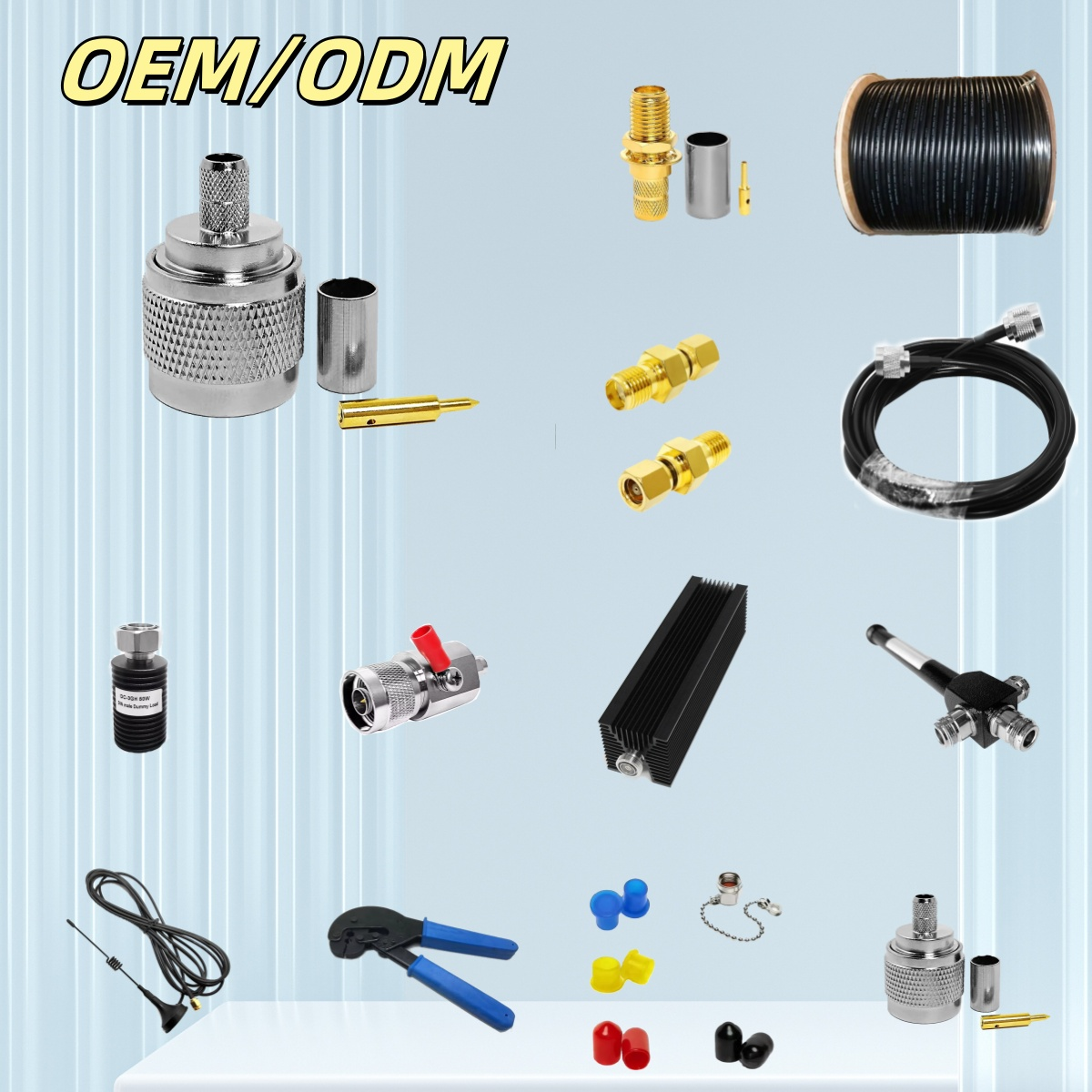
High-frequency system integration demands high physical and electrical reliability from interconnected transmission paths. A common vulnerability in telecommunications towers, laboratory test bays, and rugged aerospace chassis is treating the interconnecting coax as a simple point-to-point wire rather than a precision wave-guiding component. Sourcing custom links requires engaging with professional cable assembly manufacturers who possess the diagnostic instrumentation and tooling discipline necessary to maintain continuous characteristic impedance. A minor structural deviation during strip-and-crimp preparation alters coaxial dielectric spacing, triggering severe voltage standing wave ratio spikes and elevated insertion loss.
When designing custom signal routing, system architects must draft a comprehensive technical file before soliciting proposals from rf cable assembly manufacturers. Relying on generic component catalogs frequently results in physical mismatches during installation or phase drift during thermal cycling. A verified build package must define not only the physical interface and overall length but also phase-matching tolerances, mechanical strain relief, maximum allowable attenuation at high-frequency boundaries, and explicit shielding effectiveness parameters.
Technical Specifications Across Demanding Vertical Sectors
coaxial requirements change drastically when shifting from commercial telecommunications to life-critical diagnostics or combat-ready aerospace equipment. Sourcing managers must screen potential partners based on their certified compliance within these highly specialized industries, ensuring that candidate cable assembly manufacturers possess the exact quality management credentials required for the end application.
Performance Metric
Commercial Telecommunications
Medical Diagnostic Systems
Military and Aerospace Systems
Primary Industry Certification
ISO 9001 standard controls
ISO 13485 medical compliance
AS9100D aerospace standards
Temperature Survivability Range
-40°C to +85°C standard range
0°C to +60°C controlled
-55°C to +125°C or higher
Cable Jacket Material Focus
Economy PVC or Polyethylene
Biocompatible, USP Class VI silicone
Low-smoke zero-halogen (LSZH), PTFE
Structural Shielding Target
90 dB minimum isolation
Ultra-flexible double-braid mesh
Triaxial or solid copper outer conductor
Sterilization Compatibility
Not required for general use
Autoclave, EtO, or chemical wipes
Chemical agent resistant coating (CARC)
| Performance Metric | Commercial Telecommunications | Medical Diagnostic Systems | Military and Aerospace Systems |
|---|---|---|---|
| Primary Industry Certification | ISO 9001 standard controls | ISO 13485 medical compliance | AS9100D aerospace standards |
| Temperature Survivability Range | -40°C to +85°C standard range | 0°C to +60°C controlled | -55°C to +125°C or higher |
| Cable Jacket Material Focus | Economy PVC or Polyethylene | Biocompatible, USP Class VI silicone | Low-smoke zero-halogen (LSZH), PTFE |
| Structural Shielding Target | 90 dB minimum isolation | Ultra-flexible double-braid mesh | Triaxial or solid copper outer conductor |
| Sterilization Compatibility | Not required for general use | Autoclave, EtO, or chemical wipes | Chemical agent resistant coating (CARC) |
Specialized medical cable assembly manufacturers focus heavily on ultra-flexible jacket materials, low microphonic triboelectric noise, and non-magnetic materials that are compatible with MRI environments. Conversely, military cable assembly manufacturers prioritize physical ruggedness, resistance to extreme mechanical shock, high vibration profiles under MIL-STD-810H, and hermetic glass sealing to withstand high-altitude decompression.
Structural Failure Modes in Custom Coaxial Integration
Preventing field failures in complex microwave systems requires identifying physical stress points before releasing a design to production. When working with rf cable assembly manufacturers, designers must evaluate the mechanical routing path within the final enclosure. Forcing a semi-rigid or conformable cable beyond its structural physical boundaries alters the internal conductor concentricity, permanently degrading signal integrity.
Failure Category
Physical Mechanism
Technical Consequence
Engineering Prevention Method
Exceeded Bend Radius Limit
Outer shield deformation and core pinching
Impedance shifts, high VSWR, phase drift
Enforce 5x OD for flexible, 10x OD for semi-rigid
Solder Infiltration (Wicking)
Solder moves past joint under shield braid
Localized cable stiffness and brittle fracture
Optimize induction soldering heat and duration
Mismatched Phase Tuning
Variations in electrical length across runs
Phase cancellation in antenna arrays
Specify relative or absolute phase matching in RFQ
Connector Nut Over-Torque
Metal deformation of threads and reference faces
Intermittent ground contact, pin recession
Implement calibrated torque wrenches in assembly
| Failure Category | Physical Mechanism | Technical Consequence | Engineering Prevention Method |
|---|---|---|---|
| Exceeded Bend Radius Limit | Outer shield deformation and core pinching | Impedance shifts, high VSWR, phase drift | Enforce 5x OD for flexible, 10x OD for semi-rigid |
| Solder Infiltration (Wicking) | Solder moves past joint under shield braid | Localized cable stiffness and brittle fracture | Optimize induction soldering heat and duration |
| Mismatched Phase Tuning | Variations in electrical length across runs | Phase cancellation in antenna arrays | Specify relative or absolute phase matching in RFQ |
| Connector Nut Over-Torque | Metal deformation of threads and reference faces | Intermittent ground contact, pin recession | Implement calibrated torque wrenches in assembly |
During system assembly, a tight chassis corner might tempt an installer to force a sharp bend adjacent to the connector ferrule. This localized stress concentration represents a primary failure mode, causing the center pin to recede inside the dielectric over time. Qualified military cable assembly manufacturers address this vulnerability by implementing pre-formed, semi-rigid jumper runs or utilizing molded strain-relief boots that absorb external mechanical loads.
Verification Protocols and Quality Control Matrices
Relying on simple digital multimeter continuity testing is insufficient for verifying high-frequency performance. Professional rf cable assembly manufacturers implement exhaustive, instrument-driven quality control protocols on 100% of finished lots to guarantee electrical repeatability.
Quality Verification Gate
Diagnostic Equipment Utilized
Target Testing Parameter
Associated Defect Identified
Continuous Vector Network Sweep
Dual-Port Vector Network Analyzer (VNA)
Insertion loss (S21), return loss (S11)
Cable crimp defects, core damage, bad plating
Time Domain Reflectometry
High-Resolution TDR Sampling Scope
Distance-to-fault impedance profiling
Localized pinching, shield voids, internal shorts
Dielectric Withstanding Test
High-Potential (Hi-Pot) Tester
Voltage breakdown limits, leakage current
Pin-to-shield spacing issues, insulation voids
Phase Matching Verification
Calibrated Dual-Path VNA System
Phase match tolerance (e.g., ± 2° at 18 GHz)
Variations in electrical length across arrays
| Quality Verification Gate | Diagnostic Equipment Utilized | Target Testing Parameter | Associated Defect Identified |
|---|---|---|---|
| Continuous Vector Network Sweep | Dual-Port Vector Network Analyzer (VNA) | Insertion loss (S21), return loss (S11) | Cable crimp defects, core damage, bad plating |
| Time Domain Reflectometry | High-Resolution TDR Sampling Scope | Distance-to-fault impedance profiling | Localized pinching, shield voids, internal shorts |
| Dielectric Withstanding Test | High-Potential (Hi-Pot) Tester | Voltage breakdown limits, leakage current | Pin-to-shield spacing issues, insulation voids |
| Phase Matching Verification | Calibrated Dual-Path VNA System | Phase match tolerance (e.g., ± 2° at 18 GHz) | Variations in electrical length across arrays |
When reviewing proposals from medical device developers, specialized medical cable assembly manufacturers must also verify dielectric isolation under high-voltage pulses to guarantee patient safety. For military aviation links, aerospace-grade military cable assembly manufacturers perform phase-matching checks across wide temperature cycles to ensure target acquisition radar modules maintain directional accuracy under high thermal stress.
Sourcing Strategies: Sample Gates, MOQs, and Traceability
Transitioning from an engineering prototype to a high-volume production release requires structured coordination with selected cable assembly manufacturers. Attempting to scale production without a documented first-article sample gate often leads to compounding errors across assembly batches. A reliable sourcing pipeline separates the procurement cycle into distinct validation milestones:
-
Engineering Samples: Small-batch builds utilizing production-grade materials to verify physical routing, actual bend clearance, and initial electrical parameters in the real operating environment.
-
First Article Inspection (FAI): Complete dimensional, electrical, and mechanical inspection reports of the initial production-run units to confirm the assembly line matches technical drawings.
-
Documented Bill of Materials: Restricting material substitutions unless formal engineering change notices are reviewed and approved by the customer's design team.
-
Lot Traceability Retention: Keeping complete material lot numbers, operator tracking logs, and vector network analyzer sweep records on file for a minimum of five to ten years.
This structured verification prevents manufacturing bottlenecks, especially when managing high-compliance builds with military cable assembly manufacturers who must document material origin for defense-related contracts.
Advanced Manufacturing Precision and Worldpeak Production Capabilities
Securing high-frequency system performance requires an experienced manufacturing partner with advanced technical capabilities, rigorous quality control, and scalable production resources. Worldpeak delivers complete engineering development, custom prototyping, and global supply chain support for custom RF coaxial interconnect solutions.
Operating state-of-the-art multi-axis Swiss CNC turning centers and automated wire preparation lines, Worldpeak is recognized among premier cable assembly manufacturers. Worldpeak specializes in producing high-performance RF coaxial jumpers, custom multi-port wire harnesses, and hermetically sealed bulkhead connections. The manufacturing process utilizes premium certified brass, phosphor bronze, and stainless steel, paired with high-purity gold plating to ensure low contact resistance and excellent corrosion protection.
Worldpeak serves as a dependable partner for demanding industries, operating as both an agile partner for custom configurations and a high-volume supplier of standard RF jumpers. Whether collaborating as one of the trusted rf cable assembly manufacturers for telecommunications arrays, supporting complex equipment as one of the specialized medical cable assembly manufacturers, or complying with strict material traceability as one of the leading military cable assembly manufacturers, Worldpeak ensures that every assembly undergoes 100% vector network analyzer screening up to 40 GHz. From rapid prototyping to high-volume production, Worldpeak delivers reliable engineering and consistent quality to support advanced RF systems globally.





