EN
EN

tnc-male-to-tnc-female-lightning-arrester---dc---3-ghz, tnc-male-to-tnc-female-lightning-arrester---dc---3-ghz, /rf-lightning-arrester
EN
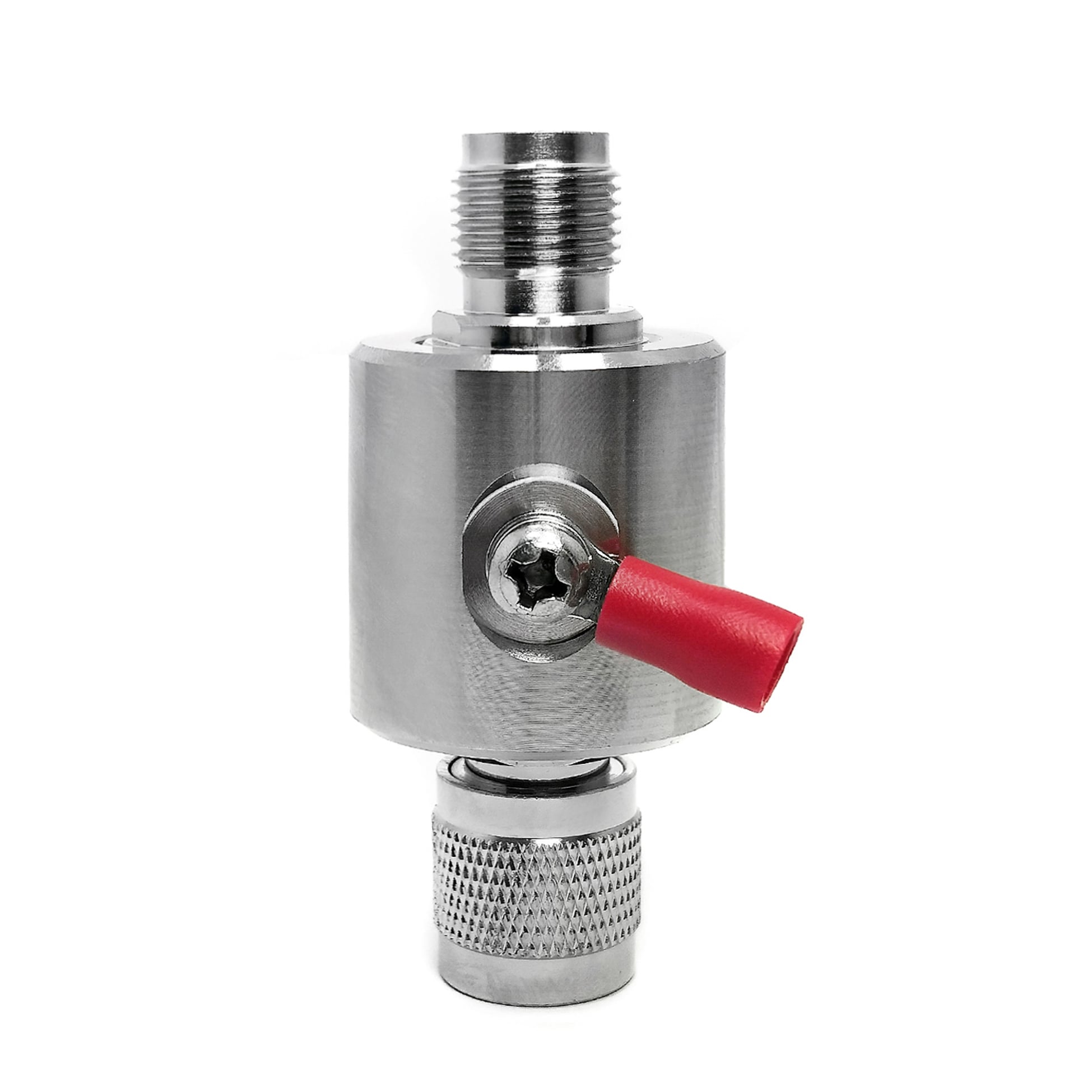
This TNC Male to TNC Female lightning arrester is a GDT based RF surge protector designed for DC - 3 GHz operation. It sits in the transmission line between the antenna and the radio equipment, diverting lightning-induced transients to ground before they reach the sensitive front end. The 50 ohm design holds insertion loss at 0.2 dB with a VSWR of 1.25 or better across the passband.
Request a Quote | Download Datasheet | Ask an Engineer
Product Overview
Designed for an inline 50 ohm coaxial route, this TNC male-to-female protection unit operates across the stated DC to 3 GHz band. Its serviceable 90 V GDT has a reference 10 kA capacity on the 8/20 us wave and connects surge energy to the earth terminal. The specified signal loss is 0.2 dB during normal RF operation.
Core Trade-off: A gas-discharge approach supports a replaceable element and a low-capacitance transmission path. Its response threshold is distinct from diode solutions, so final selection should follow the antenna-line design and installation context.
Protection Mechanism and Construction
Reference Technical Specifications
The values below are provided as product references. Verify them against the selected production configuration before installation or system commissioning.
Attribute |
Declared value |
Use note |
Connection pair |
TNC Male to TNC Female |
Compatible cable end |
Mechanical form |
Inline |
Physical layout |
Line impedance |
50 ohm |
Nominal system value |
Frequency span |
DC - 3 GHz |
Applicable range |
RF loss |
0.2 dB |
Across listed range |
VSWR |
1.25 |
Maximum |
CW power basis |
150 W |
Stated CW condition |
Protection element |
90 V |
Gas-discharge type |
Surge current basis |
10 kA (8/20 us) |
8/20 us reference |
Ground bond |
Ring terminal |
M4 bonding lug |
Body material |
Machined brass |
Surface protection |
Approximate mass |
97.8 g |
Listed mass |
Application context |
Base radio and repeater, telemetry |
Selection context |
Use the listed information as a reference and confirm the final configuration before deployment.
Engineering Comparison
Applications
Installation and Grounding Notes
OEM and B2B Support
FAQ
Q: How often does the gas discharge tube need replacement?
A: The 90 V element is referenced at 10 kA for the 8/20 us wave. Inspect it after a major event and replace it if leakage is found or the hold-off test is unsuccessful.
Q: Will this TNC Male to TNC Female lightning arrester affect my DC - 3 GHz signal?
A: The stated references are 0.2 dB insertion loss and VSWR no greater than 1.25, supporting a compatible low-impact RF path.
Q: Can I use this arrester indoors?
A: Yes. An installation may be made at the equipment side of a run or at an entry location when the system requires another grounded protection point. A TNC Male to TNC Female lightning arrester should be matched to the cable assembly and site bonding route. This RF surge protector is intended for the specified coaxial arrangement. The stated 3 GHz coaxial lightning protection range should be checked against the planned RF system. For base radio and repeater surge protection, locate the device at a suitable cable-entry or equipment-side point. A second TNC Male to TNC Female lightning arrester reference can be used when documenting the selected installation. Confirm the final production configuration before commissioning. Before installation, review the cable route, panel entry, connector access, and bonding location. Confirm that the inline body can be inspected without moving nearby equipment and that the cable has suitable support on both sides. Check the condition of weather sealing where connections are exposed. Document the selected mounting point and earth-bar connection for later maintenance. During service, inspect the ring terminal, cable jacket, connector engagement, and available clearance. If the radio cabinet, cable run, or grounding arrangement changes, reassess the installation before returning the system to normal operation. These practical checks support the specified product configuration and do not replace site procedures or final production documentation.