EN
EN

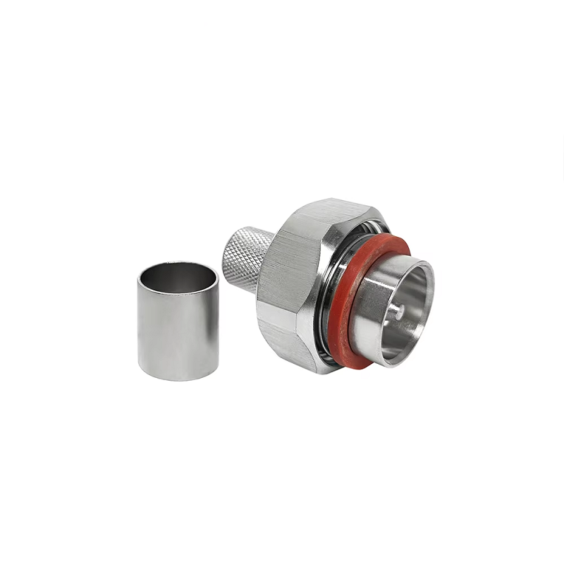
For original equipment manufacturing procurement teams and radio frequency engineers, sourcing a high-power 7/16 male connector involves far more than confirming basic thread compatibility. While a connector body may fit standard mounting hardware, unverified internal dimensional tolerances can cause impedance mismatches, high return loss, or elevated passive intermodulation (PIM) levels once installed in cellular base stations or high-power transmitter runs.
The international specification IEC 61169-4 defines the primary interface rules for the 7/16 series, specifying a 7.0 mm inner conductor diameter and a 16.0 mm outer conductor inner diameter with M29x1.5 coupling threads. However, an industry standard acts as a functional boundary rather than an exhaustive production drawing. Establishing predictable performance across production lots requires a comprehensive OEM tolerance plan that defines critical mating geometry, concentricity, surface finish, and plating thickness windows.
Distinguishing Interface Standards from Production Tolerance Plans
An OEM drawing for a 7/16 male connector translates standard interface requirements into precise machining parameters. While IEC 61169-4 ensures intermateability across manufacturers, it leaves specific internal mechanical allowances, housing runouts, and cable attachment geometries to the OEM specification.
Machining controls must account for base metal turning tolerances as well as subsequent plating layers. Applying silver or tri-metal coatings adds microscopic thickness layers that alter thread engagement and center pin dimensions. Defining whether dimensional limits apply before or after surface finishing prevents unexpected tight mating conditions or loose center contacts in final assemblies.
Critical Dimensional Features on High-Power RF Interfaces
Achieving consistent precision 7/16 din manufacturing requires prioritizing dimensions based on their impact on mechanical alignment and RF performance.
| Feature Category | Critical Dimensions | Primary Impact | Recommended OEM Control Method |
| Mating Interface Geometry | 7.0 mm Pin / 16.0 mm Outer Diameter | Interchangeability & Impedance Continuity | Go/No-Go Gauge Sets & Optical Comparators |
| Center Contact Alignment | Pin Protrusion / Pin Diameter | Contact Retention Force & VSWR Stability | Coordinate Measuring Machines (CMM) & Pin Gauges |
| Coupling Thread Geometry | M29 x 1.5 Thread Pitch | Torque Transfer & Vibration Resistance | Precision Thread Ring Gauges & Thread Micrometers |
| Dielectric Concentricity | PTFE Insulator Radial Runout | Electric Field Uniformity & PIM Mitigation | SAM/Optical Inspection & Precision Tooling |
| Plating Uniformity | Silver / Tri-Metal Layer Depth | Contact Resistance & Corrosion Prevention | X-ray Fluorescence (XRF) Coating Gauges |
Maintaining precise concentricity between the 7.0 mm center pin and the 16.0 mm outer conductor ground plane is essential. Minor eccentricities disrupt the uniform 50-ohm characteristic impedance profile, creating internal signal reflections at higher operating frequencies.
Practical Machining Limits and Tooling Capabilities
Holding tight tolerances requires balancing manufacturing costs with functional performance requirements. Machining brass connector bodies on multi-axis CNC Swiss-type lathes routinely yields mechanical tolerances within tight margins.
Extremely tight tolerances should be reserved for features that directly impact the RF path, center pin retention, or environmental sealing. Allowing standard commercial tolerances on non-mating outer surfaces optimizes production efficiency without compromising electrical performance.
Combining Dimensional Inspection with Functional Gauging
Physical measurements alone cannot fully guarantee smooth mechanical mating and low insertion loss. Comprehensive rf connector quality control relies on a dual-track validation approach combining direct dimensional metrology with functional interface gauging.
-
Direct Coordinate Measurement: Optical measurement tools and CMM systems verify complex internal profiles, shoulder steps, and chamfer angles against CAD models.
-
Functional Interface Gauging: Calibrated Go/No-Go pin and thread gauges confirm that male coupling nuts engage smoothly without binding or excessive play.
-
Reference Plane Verification: Depth indicators measure center pin protrusion and recession relative to the outer conductor reference plane, ensuring consistent contact pressure when torqued to specified limits.
Integrating functional gauging into quality control protocols prevents out-of-spec parts from entering assembly lines, protecting against field mating failures and connector damage.
Connecting Physical Tolerances to RF Signal Integrity
Dimensional accuracy directly affects electrical performance. Misaligned center pins, uneven plating, or distorted dielectric supports alter transmission line characteristics, degrading system efficiency in high-power applications.
-
Impedance Continuity: Variations in center pin diameter or outer conductor bore shift local impedance away from 50 ohms, increasing return loss.
-
Passive Intermodulation (PIM): Microscopic air gaps or uneven contact pressure across mating surfaces generate non-linear intermodulation distortion under high transmit power.
-
Voltage Standing Wave Ratio (VSWR): Dimensional stack-up errors create internal reflections, reducing forward power transfer efficiency.
Validating completed cable jumpers or equipment interface jacks with Vector Network Analyzer (VNA) sweep testing confirms that physical machining accuracy translates into low insertion loss and high return loss performance across the target frequency band.
Technical Procurement Checklist for OEM Connectors
-
Specify Standard References: Formally cite iec 61169 4 connector tolerance guidelines along with drawing revision levels in the purchase specification.
-
Mark Critical-to-Function Dimensions: Highlight key 7/16 male connector interface dimensions on engineering prints, including pin protrusion and thread profiles.
-
Define Finished Condition Rules: Clarify whether drawing dimensions apply before or after plating, and define plating thickness limits.
-
Establish Datum Systems: Reference clear geometric datums for concentricity, runout, and axial positioning callouts.
-
Request Pre-Shipment Inspection Data: Require lot-traceable measurement records, including CMM dimensional reports and functional gauge results.
-
Verify Electrical Pass Criteria: Define mandatory frequency ranges, VSWR thresholds, and PIM testing requirements for complete cable assemblies.
Enhancing Systems Quality Through Controlled Manufacturing
Establishing precise tolerance controls transforms standard connector sourcing into a predictable engineering process. Defining critical mating dimensions, accounting for plating thicknesses, and combining metrology with functional gauging ensures stable RF performance, repeatable installation torque, and long-term operating reliability.
To support high-power wireless networks and broadcast infrastructure, WORLDPEAK supplies precision-machined RF connectors, adaptors, and custom cable assemblies. Manufactured using multi-axis CNC turning equipment and verified through automated CMM metrology, VNA sweep testing, and PIM analysis, these factory-controlled solutions deliver consistent impedance matching and low loss for critical communications applications worldwide.