 EN
EN

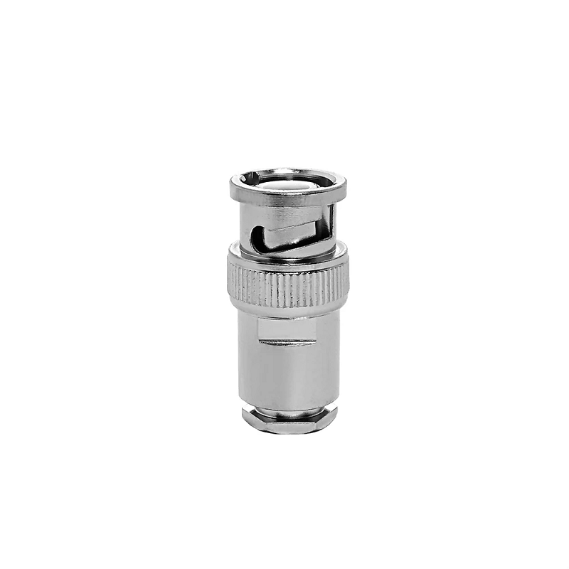
The coaxial interface known as the bnc plug male remains a core standard across laboratory instrumentation, radio frequency links, video production, and commercial test fixtures. Defined by its signature two-stud bayonet locking mechanism, the connector provides secure physical mating with a rapid quarter-turn rotation. In demanding test and transmission environments, this component acts as a direct extension of the transmission line. Selecting an RF connector solely by visual footprint or physical fit frequently produces hidden impedance mismatches, high return loss, and premature mechanical wear.
System reliability requires balancing electrical impedance, operating frequency, contact metallurgy, mechanical geometry, and coaxial cable dimensions. A professional installation avoids relying on catalog photos alone and focuses on the complete transmission path.
Operational Advantages of the Bayonet Coupling Mechanism
Rapid deployment and repeatable contact retention explain why the bnc plug interface continues to dominate test benches and broadcast racks. Threaded alternatives like SMA or Type-N connectors require calibrated torque wrenches to prevent over-tightening or junction gaps. In contrast, the bayonet mechanism incorporates internal spring washers that maintain continuous axial pressure against the mating jack lugs.
-
Audible and tactile feedback confirms full engagement without secondary torque verification.
-
Field operations accelerate when switching signal paths across dense patch panels.
-
Bayonet lugs decouple rotational torque from the internal center contact, minimizing pin shearing during mating.
-
The slotted outer spring body delivers consistent ground shield contact across broad temperature ranges.
Mating Cycle Endurance and Contact Wear Dynamics
Industrial connector specifications establish an endurance rating of 500 mating cycles for high-reliability components conforming to MIL-STD-348 and IEC 61169-8 standards. Achieving this operational lifespan depends heavily on mechanical alignment, contact plating thickness, and handling practices.
Gold plating over nickel on the center contact pin preserves low contact resistance and protects against oxidation. In contrast, the bayonet body and outer shell rely on durable nickel or silver plating to resist friction galling. Premature contact failure typically stems from mechanical abuse rather than legitimate electrical breakdown. Pulling assemblies directly by the coaxial jacket imparts severe side-loading forces to the connector body, warping the bayonet slots and misaligning the internal female contact fingers on mating jacks. Incorporating proper strain-relief boots and enforcing scheduled maintenance cycles ensures the bnc plug male maintains its baseline insertion loss over years of field deployment.
Mechanical Form Factors for Dense Equipment Packaging
Routing coaxial cables through crowded equipment chassis requires matching the connector form factor to physical clearances and service boundaries.
Straight cable plugs serve as the baseline configuration for test bench leads, calibration jumpers, and patch cords. This structure facilitates a clean transmission path with minimal structural discontinuity, though it requires sufficient linear clearance behind equipment panels to satisfy minimum cable bend radius limits.
Right-angle configurations divert cable routing by 90 degrees directly at the rear entry. This geometry enables compact installation inside shallow racks, surveillance housings, and field communication cases. While convenient for routing, right-angle designs introduce internal geometric transitions that can elevate Voltage Standing Wave Ratio (VSWR) at higher operating frequencies.
Bulkhead and panel-mount interfaces establish a fixed equipment boundary. A panel-mounted receptacle provides structural support, allowing the external bnc plug male on the cable assembly to absorb routine mating wear as a field-replaceable consumable.
Impedance Matching: 50 Ohm versus 75 Ohm Parameters
Impedance matching stands as the single most critical electrical decision in RF system assembly. Two visually identical components may feature entirely different characteristic impedances, leading to signal degradation when cross-mated.
A 50 Ω bnc plug male is engineered for high-frequency telecommunications, RF laboratory instruments, wireless transmitters, and military radios. The internal interface utilizes a continuous PTFE dielectric insulator supporting the center contact pin.
A 75 Ω bnc plug is optimized for video distribution, broadcast infrastructure, digital audio, and telecommunication carrier networks. To maintain 75 Ω impedance within the fixed bayonet shell envelope, manufacturers minimize or alter the internal dielectric layer, creating an air-dielectric boundary around the contact pin.
Design Parameter
50 Ohm BNC Architecture
75 Ohm BNC Architecture
Primary Application
RF Communications, Laboratory Instruments, Antenna Feeds
Professional Video, SDI Broadcast, Telecommunications
Frequency Range
DC to 4 GHz (Standard) / Up to 12 GHz (Precision)
DC to 1 GHz (Standard) / Up to 12 GHz (12G-SDI)
Internal Dielectric
Solid PTFE Surrounding the Center Pin
Air Dielectric or Minimal Support Ring
Pin Outer Diameter
Approximately 1.35 mm to 1.40 mm
Approximately 1.30 mm to 1.32 mm
Mechanical Danger
Insertion into 75 Ω jack will permanently spread female contacts
Mates with 50 Ω socket without damage, but introduces severe reflections
System Risk
Return loss degradation in video circuits
Signal distortion, packet loss, and high VSWR
| Design Parameter | 50 Ohm BNC Architecture | 75 Ohm BNC Architecture |
|---|---|---|
| Primary Application | RF Communications, Laboratory Instruments, Antenna Feeds | Professional Video, SDI Broadcast, Telecommunications |
| Frequency Range | DC to 4 GHz (Standard) / Up to 12 GHz (Precision) | DC to 1 GHz (Standard) / Up to 12 GHz (12G-SDI) |
| Internal Dielectric | Solid PTFE Surrounding the Center Pin | Air Dielectric or Minimal Support Ring |
| Pin Outer Diameter | Approximately 1.35 mm to 1.40 mm | Approximately 1.30 mm to 1.32 mm |
| Mechanical Danger | Insertion into 75 Ω jack will permanently spread female contacts | Mates with 50 Ω socket without damage, but introduces severe reflections |
| System Risk | Return loss degradation in video circuits | Signal distortion, packet loss, and high VSWR |
Physical cross-mating between these two families creates irreversible hardware damage. The larger center pin of a 50 Ω plug will over-expand and destroy the precision contact spring fingers inside a delicate 75 Ω jack.
Cable Integration: RG58 BNC Connector versus RG6 BNC Connector
Coaxial cable geometry governs connector shell dimensions, crimp ferrule diameters, and contact pin dimensions. Standardizing connector models without verifying exact cable specifications leads to crimp failure and poor RF shielding.
The rg58 bnc connector terminates 50 Ω flexible coax, such as RG-58, RG-58A/U, and equivalent commercial low-loss variants. With a nominal jacket diameter near 5.0 mm (0.195 inches) and an internal 20 AWG solid or stranded conductor, this assembly serves as the workhorse for test bench leads and two-way radio patch cords. Precision hex dies must compress the ferrule without crushing the internal foam or solid PE dielectric.
The rg6 bnc connector serves 75 Ω video, security, and broadcast transmission lines. RG-6 features a significantly thicker outer jacket (approximately 6.8 mm / 0.270 inches), a larger 18 AWG center conductor, and combination foil/braid shielding. The ferrule and internal cavity of an rg6 bnc connector must accommodate this increased bulk. Attempting to force an rg58 bnc connector onto RG-6 stock causes dielectric crushing, pin misplacement, and shield discontinuity.
Termination Methodology: Crimp vs Solder Standards
Precision termination methods directly dictate contact resistance, pull-off strength, and high-frequency VSWR.
Performance Metric
Controlled Hex Crimp Termination
Solder Termination Assembly
Assembly Speed
High efficiency; ideal for production line scaling
Slower; suited for field repairs and lab prototypes
Mechanical Consistency
Highly repeatable using calibrated ratcheting tools
Operator-dependent quality and fillet shape
Thermal Risk
Zero thermal stress on internal PTFE dielectrics
Risk of dielectric warping or solder wicking
Field Serviceability
Requires specific crimp tool and die set
Requires heat source and soldering equipment
Shield Retention
Uniform 360-degree ferrule compression
Mechanical clamp or manual shield solder tabbing
| Performance Metric | Controlled Hex Crimp Termination | Solder Termination Assembly |
|---|---|---|
| Assembly Speed | High efficiency; ideal for production line scaling | Slower; suited for field repairs and lab prototypes |
| Mechanical Consistency | Highly repeatable using calibrated ratcheting tools | Operator-dependent quality and fillet shape |
| Thermal Risk | Zero thermal stress on internal PTFE dielectrics | Risk of dielectric warping or solder wicking |
| Field Serviceability | Requires specific crimp tool and die set | Requires heat source and soldering equipment |
| Shield Retention | Uniform 360-degree ferrule compression | Mechanical clamp or manual shield solder tabbing |
Production environments rely primarily on crimp configurations. Using a calibrated ratcheting crimp tool equipped with the exact cavity size specified for the rg58 bnc connector or rg6 bnc connector ensures gas-tight shield grounding without rupturing individual braid wires.
Best Practices for RF Assembly and Quality Control
Achieving consistent return loss and reliable mating cycles requires disciplined assembly procedures:
-
Verify the printed part numbers on both the cable jacket and connector packaging before stripping.
-
Utilize automated or calibrated three-stage rotary stripping tools to ensure exact strip dimensions for the jacket, braid, and dielectric.
-
Inspect stripped braid wires to confirm no loose strands touch the center pin, preventing intermittent direct shorts.
-
Confirm the center pin snaps into the internal insulator lock ring, verifying correct axial seating before ferrule crimping.
-
Verify crimp ferrule dimensional accuracy with a digital micrometer to detect tool wear or die looseness.
-
Conduct vector network analyzer (VNA) sweep testing across the target frequency band to validate insertion loss and VSWR thresholds.
Precision Manufacturing and OEM Capabilities with Worldpeak
High-volume RF infrastructure demands structural consistency, strict alloy compliance, and traceable quality verification across every delivered lot. As an established RF connector manufacturer and supply chain partner, Worldpeak delivers comprehensive OEM and ODM solutions across 50 Ω and 75 Ω product families. Advanced automated CNC multi-axis turning centers maintain critical machining tolerances within ±0.005 mm, ensuring that every bnc plug male delivers smooth bayonet engagement and reliable contact retention compliant with international interface standards.
The engineering facilities at Worldpeak execute comprehensive testing protocols, including network analyzer testing up to 12 GHz for precision micro-loss configurations, salt spray corrosion verification, and mechanical mating endurance validation. With flexible supply chain customization, tailored impedance tuning, and dedicated cable assembly services for both rg58 bnc connector and rg6 bnc connector configurations, Worldpeak supports global industrial clients with reliable connectivity from prototyping to multi-container export deliveries.





