 EN
EN

7/16 DIN Connector Guide: High-Power RF Standard
2026/09/24
Choose a 7 16 connector for high-power RF: compare DIN and Type N, protect PIM margin, and apply field installation checks.
2026/09/01
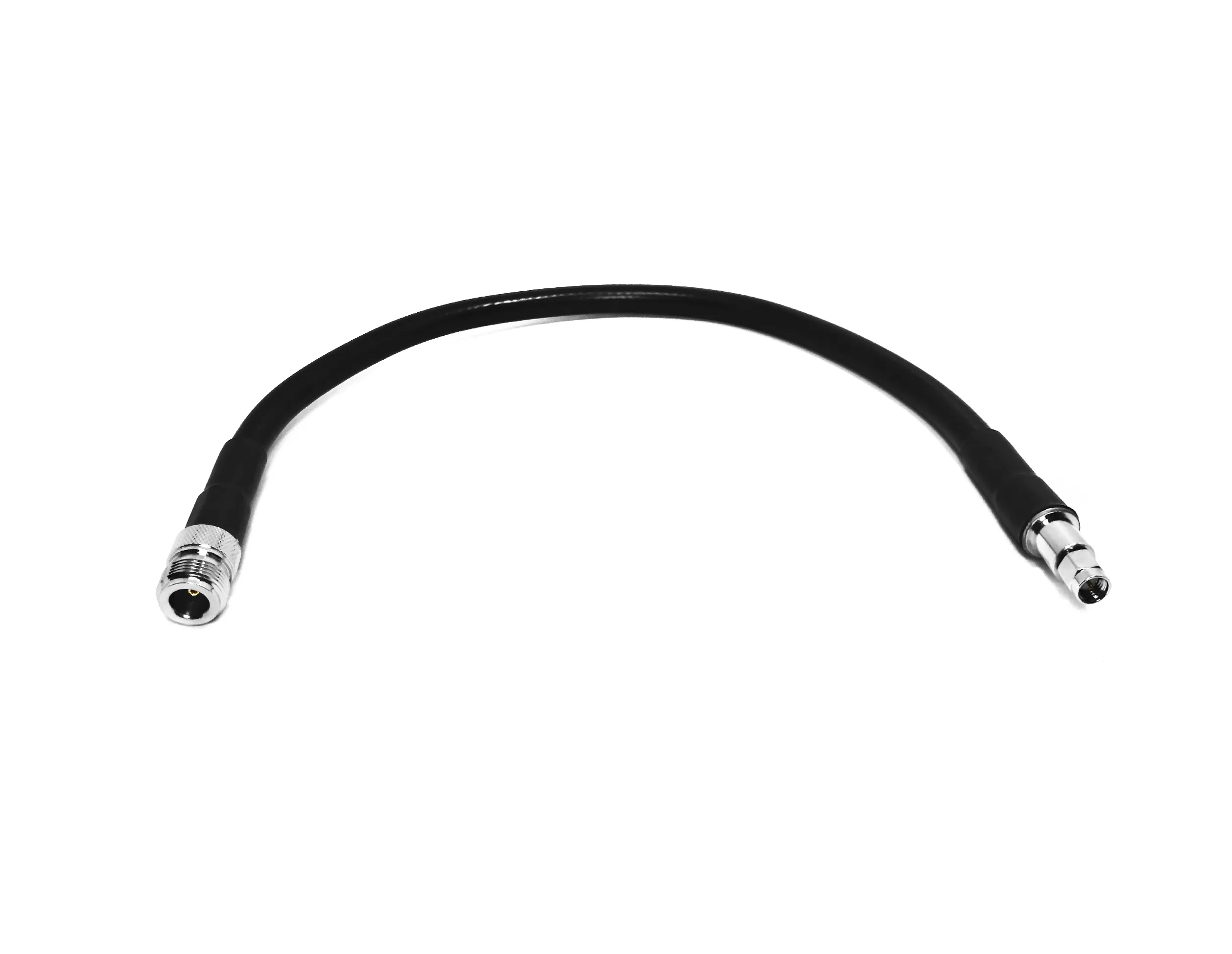
Standard off-the-shelf coaxial lines work well enough for standard bench testing, but complex electronic architectures demand much tighter tolerances. From high-resolution medical imaging equipment to harsh aerospace radar systems, relying on generic patch cords often introduces unwanted attenuation, impedance mismatches, and early failure under environmental stress. Building robust custom rf cable assemblies bridges the gap between basic component routing and uncompromised signal integrity.
Successfully taking a bespoke cable design from concept to full production requires balancing electrical performance, mechanical flexibility, and material compliance. Understanding how conductor geometry, shielding construction, and termination mechanics interact simplifies the sourcing process for high-reliability systems. Here is a clear look into the technical considerations, manufacturing phases, and stringent quality demands behind modern RF cable assembly projects—with a dedicated focus on specialized medical cable assemblies.
The success of any custom coax cable project hinges on setting strict baseline specifications before striking an arc or stripping a sleeve. Vague requirements often lead to phase jitter, signal leakage, or premature strain failure in the field.
Signal loss and reflection dictate how clean a signal remains across long transmission lines. Evaluating electrical limits requires close attention to several key parameters:
Impedance Control: Maintaining a tight 50-ohm or 75-ohm character across the entire assembly prevents signal reflections. Time Domain Reflectometry (TDR) testing verifies physical symmetry along the entire cable run.
VSWR and Return Loss: A quality custom rf cable assemblies build targets a Voltage Standing Wave Ratio (VSWR) below 1.20:1 across primary operational bands, minimizing power bounce back into sensitive transmitters.
Attenuation Limits: Dielectric selection dictates insertion loss over distance. Higher operational frequencies require expanded center conductors or micro-porous PTFE dielectrics to keep signal decay minimal.
Phase Matching: Multi-channel antenna arrays and phased radar modules require precise electrical length matching, often held within +/- 1 to +/- 5 degrees across matching pairs.
Cables rarely rest in climate-controlled, stationary cabinets. Mechanical routing constraints dictate outer jacket flexibility, minimum bend radiuses, and strain relief mechanics. Outdoor cellular infrastructure calls for UV-resistant polyurethane or PE jacketing, whereas high-temperature military bays mandate FEP or PTFE outer layers capable of handling temperatures up to +200°C.
Selecting the right raw materials forms the second major pillar of durable cable assembly manufacturing. Balancing physical durability against manufacturing cost ensures long-term field stability.
Choosing the primary transmission line sets the foundation for electrical behavior:
Flexible RG-Type Lines: Cost-effective and highly flexible for tight cabinet routing, though higher insertion loss limits their use over long distances at high frequencies.
Low-Loss LMR Series: Incorporates foil shielding and closed-cell foam dielectrics to drastically lower attenuation across sub-6 GHz wireless networks.
Semi-Rigid and Conformable Lines: Solid outer copper tubing maximizes RF shielding effectiveness (>100 dB isolation), making a conformable custom coax cable ideal for precision microwave modules and test sets.
Matching the connector interface—whether SMA, BNC, Type N, MCX, or precision 2.92mm—depends on maximum operating frequency and physical locking requirements. Contact plating directly influences insertion durability and contact resistance. Heavy gold plating over nickel provides superior conductivity and oxidation resistance for military and industrial gear, while silver plating handles higher average power loads without localized thermal buildup.
Transitioning from raw materials to a finished RF cable assembly demands microscopic mechanical precision. High-frequency signals travel along the outer skin of the center conductor, meaning the slightest nick or burr degrades performance immediately.
Modern cable assembly manufacturing uses automated laser or rotary stripping equipment to cut outer jackets, braid shields, and dielectric cores to sub-millimeter tolerances. Maintaining uniform strip lengths ensures the center contact seats perfectly against the internal dielectrics during crimping or soldering.
Standardized production steps prevent field defects:
Precision cable stripping with zero strand scoring on braided shields.
Controlled soldering or pneumatic crimping of center contacts to maintain mechanical pull strength.
360-degree solder clamping or heavy crimping of outer ferrule sleeves for total shield continuity.
Microscopic inspection of mating faces to verify clean contact positioning and zero solder flash.
Few industries place higher demands on interconnect systems than healthcare. Designing medical cable assemblies goes far beyond basic electrical signal transmission, requiring strict alignment with patient safety and hygienic regulatory standards.
Interfacing near or on patients requires materials compliant with ISO 10993 standards. Outer jackets must use medical-grade TPU, silicone, or specialized PVC compounds that avoid toxic plasticizers or leaching chemicals. Raw gold contact plating remains the industry choice for non-reactive, non-allergenic contact surfaces.
Medical environments subject cables to repeated, aggressive sterilization protocols:
Steam Autoclaving (121°C to 134°C): Demands high-temp jacket materials like medical silicone or cross-linked polymers that resist thermal softening.
Ethylene Oxide (EtO) Gas & Chemical Wipes: Requires chemically inert outer jackets that do not absorb harsh chemical agents or degrade under continuous wipe-downs.
Gamma Radiation: Mandates radiation-stable polymers that resist yellowing, cracking, or embrittlement over time.
Operating inside or near Magnetic Resonance Imaging (MRI) suites requires completely non-magnetic hardware. Standard connectors containing nickel underplates or ferrous steel bodies create dangerous magnetic pull forces and severe image distortion artifacts. Deploying a specialized non-magnetic RF cable assembly built with custom brass or beryllium copper hardware ensures complete MRI compatibility without disrupting sensitive field scans.
A dependable custom coax cable must undergo thorough end-of-line verification before entering service. Skipping testing stages risks introducing intermittent faults into complex field systems.
Visual and Dimensional Inspection: 100% inspection under optical magnification to check pin depth, plating continuity, and sleeve crimp geometry.
Vector Network Analyzer (VNA) Sweeps: Full frequency sweeps measuring VSWR, insertion loss, and phase angle across total operating bandwidths.
Dielectric Withstanding Voltage (Hi-Pot): High-voltage insulation testing to ensure zero dielectric breakdown between center conductors and outer shields.
Mechanical Retention Pull Testing: Sample destructive pull tests verifying crimp joint retention forces meet stringent military and industrial standards.
Navigating complex custom cabling projects demands working with manufacturing partners who combine deep RF engineering expertise with flexible production capacity. High-mix, low-volume prototype builds require the same level of quality control and material traceability as large-scale production runs.
Suppliers such as Worldpeak focus on comprehensive cable assembly manufacturing, delivering tailored coaxial connectivity solutions for industrial automation, telecom infrastructure, and specialized healthcare equipment. Utilizing ISO 9001-certified facilities, advanced automated processing equipment, and 100% VNA electrical testing on every production batch, Worldpeak ensures consistent performance and complete material traceability from prototype design to full volume delivery.
By prioritizing precise geometric stripping, robust material selection, and rigorous end-of-line testing, engineers can confidently specify custom rf cable assemblies built to withstand extreme mechanical stress while delivering uncompromised signal fidelity.

2026/09/24
Choose a 7 16 connector for high-power RF: compare DIN and Type N, protect PIM margin, and apply field installation checks.

2026/09/24
Compare TNC connector types, specs and applications, including RP-TNC, bulkhead options, vibration performance and adapter selection.

2026/09/24
Understand MMCX connector basics, RF limits, and how to choose the right coaxial interface for compact systems.

2026/09/24
Understand RP-SMA connector polarity, mating rules, frequency checks, and OEM termination options for reliable RF builds.

2026/09/24
Choose the right bnc male connector for RF, CCTV and test systems with clear 50Ω vs 75Ω, type and installation guidance.

2026/09/24
Compare LMR400 specs, cable loss, uses, connectors and RG8/RG213 alternatives with a practical RF loss-budget method.