EN
EN

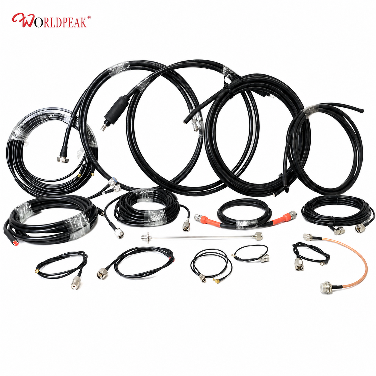
For an engineering buyer or procurement officer, the unit purchase price of an RF coaxial cable assembly represents only a fraction of its total deployed cost. The hidden, often budget-draining expenses emerge after shipment delivery on the factory floor or at field installation sites: measuring and cutting bulk cable, manually stripping insulation, crimping or soldering delicate connectors, adjusting tight bend radii, inspecting manual assembly workmanship, and retesting failing signal links. Procuring a factory-finished, custom coaxial cable assembly shifts these variable, labor-intensive tasks upstream into a controlled precision manufacturing environment.
While standard off-the-shelf patch cords make sense for benchtop testing or non-critical, low-frequency connections, high-density equipment builds require a far more rigorous approach. When an assembly line operates under tight space constraints, strict routing clearances, environmental sealing requirements, or aggressive high-frequency performance targets, specifying a purpose-built RF coaxial cable assembly directly reduces secondary processing labor at receiving stations and final assembly lines.
Uncovering the Hidden Burden of Secondary Processing
Secondary processing encompasses every manual operation required to transform bulk raw wire and loose connectors into a fully functional, installable interconnect system. Common line-side modifications include:
-
Manual Cutting and Stripping: Measuring raw cable, stripping dielectrics, and exposing inner braid conductors by hand.
-
Line-Side Connector Termination: Soldering or crimping connector contacts under inconsistent shop-floor conditions.
-
Labeling and Heat Shrinking: Adding identification sleeves, directional arrows, or weatherproofing shrink boots manually.
-
Trial-and-Error Cable Routing: Forcing generic cable lengths around internal chassis walls, leading to pinched jackets or sharp bends.
-
On-Site Electrical Verification: Attempting post-assembly continuity or basic RF sweeps without factory-grade automated test equipment.
Every additional human touch adds operational labor costs, extends production lead times, and introduces dimensional or electrical variability into the build system.
The burden becomes especially problematic when technicians attempt to adapt generic cables to complex system enclosures. A connector may match the mating interface on paper, yet remain entirely inaccessible to a torque wrench once installed inside a crowded chassis enclosure. Similarly, a cable length that seems adequate on a flat workbench might lack the necessary service loop clearance oncerouted through bulkhead panel cutouts.
When dealing with high-frequency transmission lines, the completed interconnect must maintain tight insertion loss and VSWR (Voltage Standing Wave Ratio) limits across its entire operating bandwidth. These two critical RF parameters evaluate the overall impedance stability of microwave cable assemblies. Benchtop testing bulk cable alone can never guarantee the high-frequency performance of a completed cable-and-connector system once field assembly is complete.
Strategic Customization Points That Remove Manual Line-Side Rework
Precision Cut Lengths Arrive Ready for Installation
Engineering drawings specify exact end-to-end lengths, reference measurement points, allowable dimensional tolerances, and routing pathways prior to mass production. Factory cutting eliminates trial-and-error trimming on the assembly line. Engineering teams avoid two costly pitfalls: excessive cable slack that clutters cabinet space and forces improper bend radii, or overly tight runs that strain delicate soldered PCB launches.
Connector Selection Resolved Before Component Release
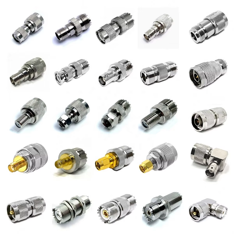
Connector gender, interface configuration (such as SMA, N-Type, BNC, or 4.3-10), mounting orientation (straight vs. 90-degree right angle), and coupling clearance are decisions best finalized in CAD software alongside mating chassis hardware. Ordering a custom coaxial cable assembly integrates these specifications into a single part number. The immediate result is a drastic reduction in adapter purchases, fewer engineering change orders, and zero risk of technicians mating incompatible connectors to undersized coaxial lines.
Integrated Mechanical Protection and Environmental Sealing
Strain relief boots, weatherproofing shrink tubes, cable breakouts, part marking sleeves, and specialized packaging can be planned alongside spatial route profiles and real-world handling conditions. For instance, an outdoor coaxial cable assembly deployed on cellular base station towers or coastal radar mounts demands specialized UV-stabilized jackets, water-blocking adhesive shrink boots, and corrosion-resistant plating choices. Treating these environmental protection measures as field add-ons introduces manual errors and makes lot traceability difficult to maintain.
Factory RF Acceptance Focused on the Finished Interconnect
Receiving a factory-tested RF coaxial cable assembly simplifies procurement handoffs and quality control procedures. Verified electrical specifications define operating frequency ranges, insertion loss limits, return loss thresholds, and phase matching requirements. Insertion loss calculations account for cable attenuation per meter, connector transition losses, and overall system link budgets. Where RF power handling and thermal stability are critical, industry frameworks such as IEC 61196-1-119:2023 establish standardized RF power testing methodologies for coaxial communication lines and cable assemblies. Establishing clear test protocols before production ensures every delivered assembly meets system requirements right out of the box.
How Custom Cable Assemblies Reduce Production Overhead
| Late-Stage Assembly Activity | Problems Caused by Generic Components | Savings Delivered by Customized Assemblies |
| Manual Trimming & Stripping | Variable cut lengths, damaged inner braids, high scrap rates | Precision factory cutting and automated wire stripping |
| Line-Side Connector Assembly | Inconsistent solder joints, improper crimp pressure, high VSWR | Standardized factory termination with controlled tooling |
| Ad-Hoc Identification | Unlabeled lines, misrouted ports, delayed field maintenance | Pre-printed part numbers, revision codes, and directional tags |
| On-Site RF Troubleshooting | Undetected reflection losses, time-consuming fault hunting | 100% pre-shipment sweep testing for insertion loss and VSWR |
| Field Weatherproofing | Incomplete tape wraps, moisture ingress, premature corrosion | Factory-sealed outdoor coaxial cable assembly options |
The financial benefits extend far beyond direct technician labor hours. Eliminating secondary processing shortens work-in-process queues, reduces handoffs between procurement and assembly teams, and prevents minor component defects from delaying multi-million-dollar equipment deliveries.
Essential Elements of a Complete Purchase Specification
To ensure a smooth transition from engineering design to volume supply, a detailed purchase specification must give the interconnect manufacturer a complete, unambiguous assembly definition.
-
Connector Interfaces: State both termination ends, including exact series, gender (plug/jack), polarity (standard vs. reverse), and body orientation (straight, 45-degree, or 90-degree right angle).
-
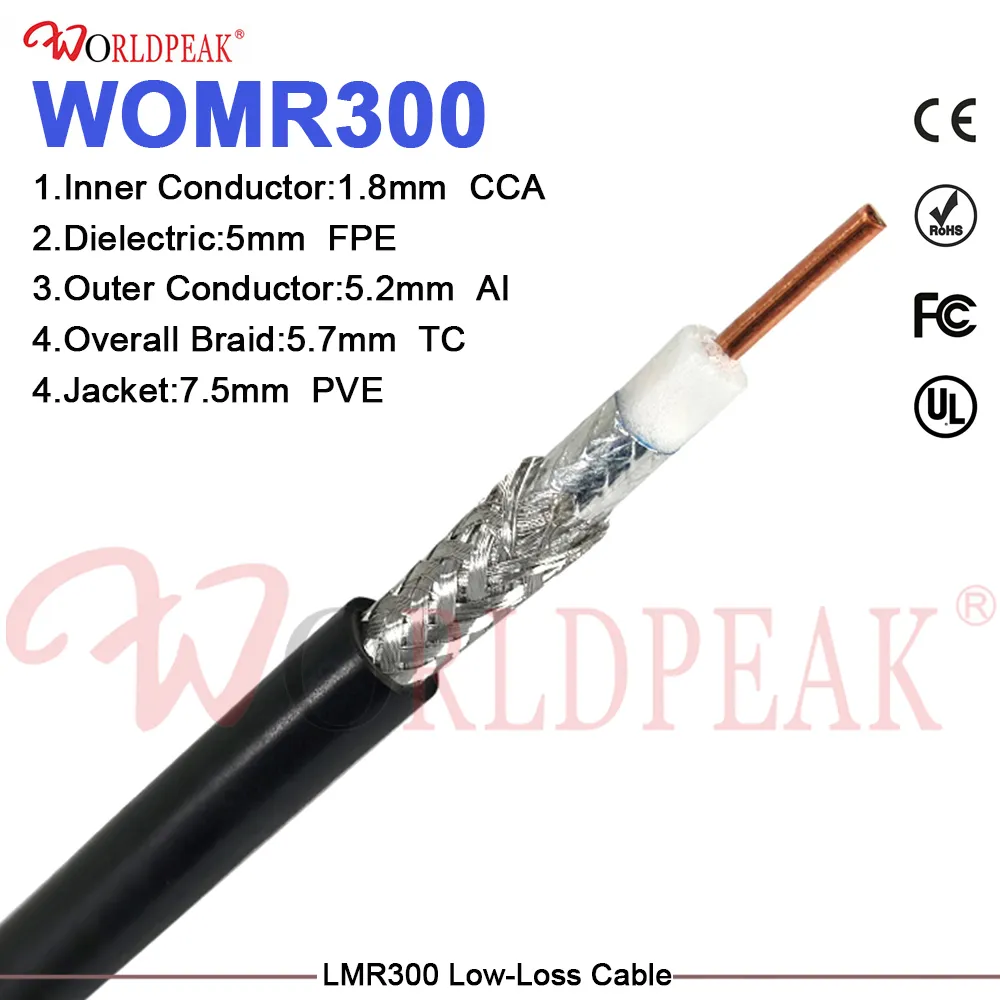
Coaxial Cable Type: Define raw cable construction parameters, center conductor stranding, dielectric material, shielding layers (braid/foil coverage), and outer jacket compound.
-
Reference Length & Tolerances: Clearly establish physical measurement reference points (e.g., tip-to-tip, connector reference plane-to-plane) and acceptable dimensional tolerances.
-
Electrical & RF Performance Metrics: Specify the full operating frequency range, maximum allowable insertion loss (dB), and target VSWR limits.
-
Environmental Exposure: For an outdoor coaxial cable assembly, specify target ingress protection ratings (IP67/IP68), temperature extremes, UV exposure levels, and salt fog resistance requirements.
-
Quality Assurance & Documentation: Define required factory testing documentation, including individual serial number tracking, VSWR sweep charts, and certificate of conformance (CoC) formats.
Collaborative Engineering for Optimizing Manufacturing Supply Chains
Engaging interconnect engineers early in the design cycle is an effective way to prevent costly secondary processing. An experienced manufacturer can identify overly tight bend radii, flag incompatible cable-to-connector pairings, suggest streamlined assembly sequences, or refine RF test limits before CAD models are locked.
Achieving consistent quality across high-frequency applications requires an established manufacturing partner capable of combining precision machining, automated assembly, and comprehensive electrical testing. Companies specializing in RF interconnect solutions provide the production flexibility and supply chain stability required to support demanding telecom, aerospace, industrial control, and medical equipment programs.
To evaluate custom cable assembly capabilities, review high-frequency interface choices, or request verified test documentation for specialized RF jumper requirements, visit